Heat pump with secondary loop air-conditioning system

a heat pump and air-conditioning technology, applied in the field of heat pump with secondary loop air-conditioning system, can solve the problems of heat exchanger freezing, front-end heat exchanger cooling down ambient air, and potential no performan

Active Publication Date: 2006-06-20
MAHLE INT GMBH
View PDF12 Cites 47 Cited by
  • Summary
  • Abstract
  • Description
  • Claims
  • Application Information

AI Technical Summary

Problems solved by technology

The problem with both these systems is that the front-end heat exchanger cools down the ambient air, which may already be very low in temperature (below 40° F.).
This causes this heat exchanger to freeze.
This results in inadequate performance and potentially no performance after a while.
This, of course, slows down the coolant warm-up rate but is insignificant and results in dumping heat into the passenger compartment with a significantly higher rate because of the compression process.

Method used


Image

  • Heat pump with secondary loop air-conditioning system
  • Heat pump with secondary loop air-conditioning system
  • Heat pump with secondary loop air-conditioning system

Examples


Embodiment Construction

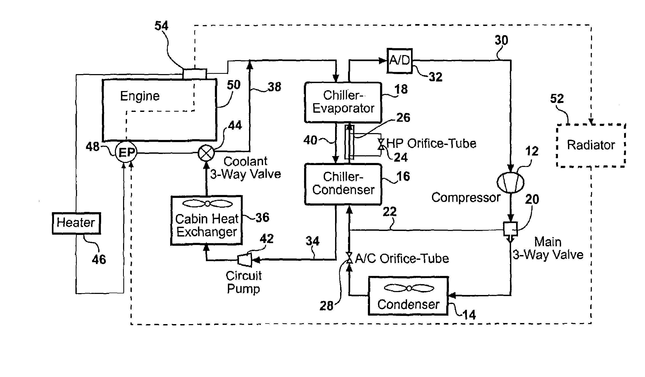
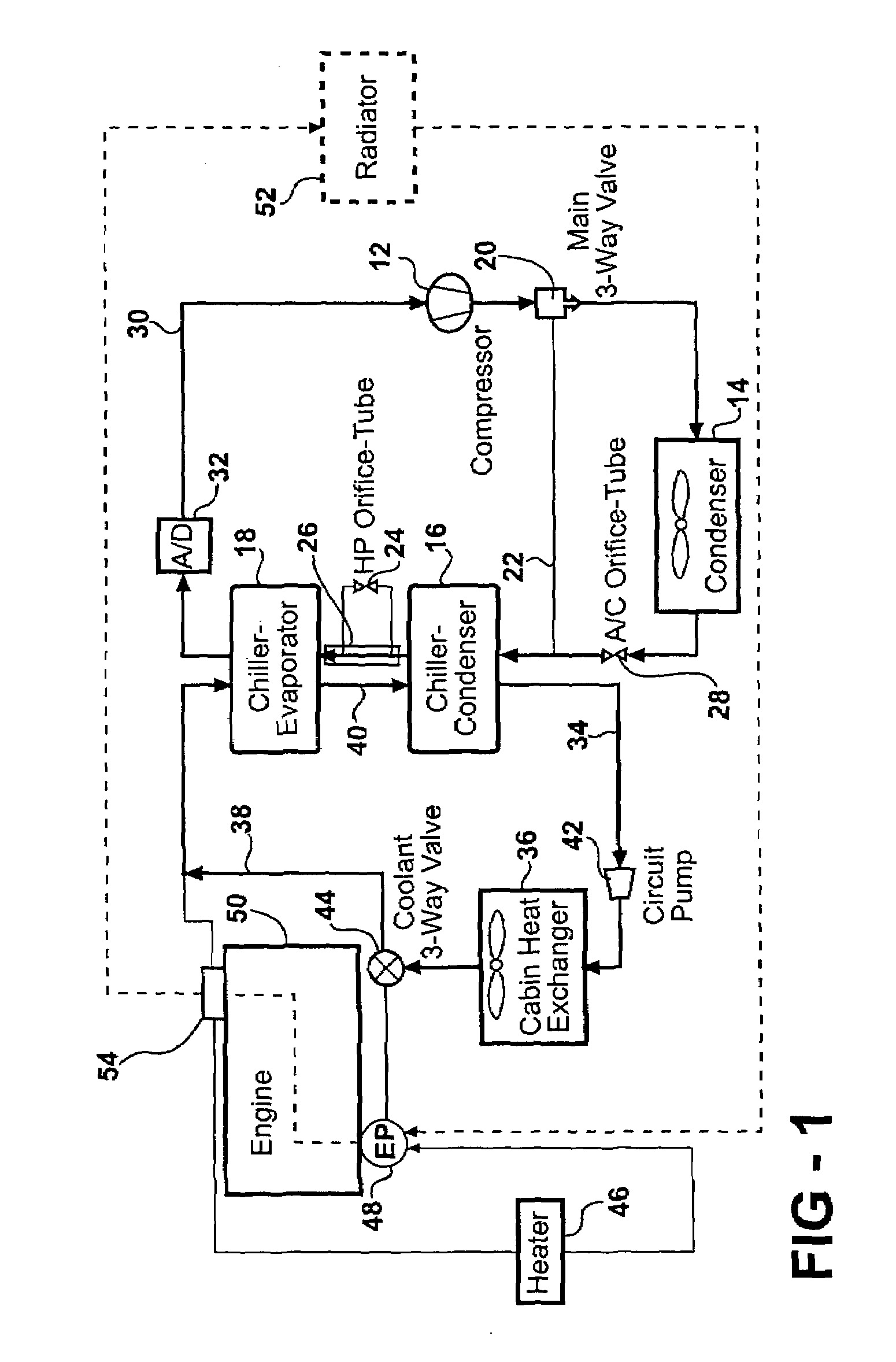
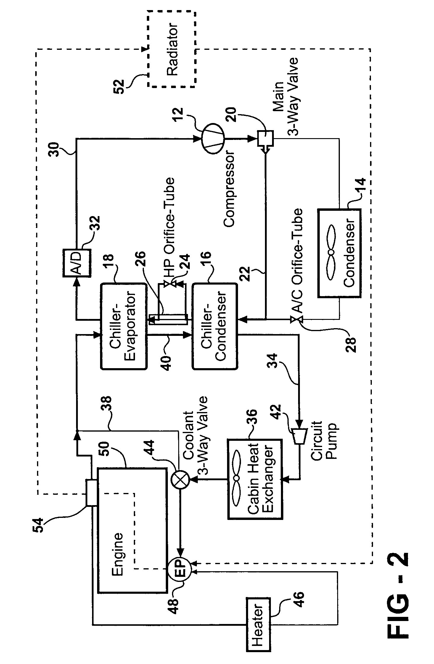
[0009]Referring to the drawings, a heater and air-conditioning assembly for a vehicle is shown schematically in FIGS. 1 and 2 wherein FIG. 1 illustrates the normal air-conditioning mode and FIG. 2 illustrates the heat pump mode.

[0010]As is customary, the system includes a compressor 12 for compressing a refrigerant and a front-end heat exchanger that acts as the traditional condenser 14 for condensing fluid from the compressor 12 in the air-conditioning mode.

[0011]A chiller-condenser 16 is disposed downstream of the condenser 14 and a chiller-evaporator 18 is disposed downstream of the chiller-condenser 16. A main three-way valve 20 is disposed between the compressor 12 and the condenser 14 for directing flow from the compressor 12 to the condenser 14 in the air-conditioning mode and for directing flow from the compressor 12 through a by-pass line 22 to the chiller-condenser 16 in the heat pump mode.

[0012]A heat pump (HP) expansion device 24, taking the form of an orifice tube, is d...


PUM


Abstract

A chiller-condenser is disposed downstream of a condenser and a chiller-evaporator is disposed downstream of the chiller-condenser. A main three-way valve is disposed between the compressor and the condenser for directing flow from the compressor to the condenser in the air-conditioning mode and for directing flow from the compressor through a by-pass line to the chiller-condenser in the heat pump mode. A heat pump (HP) expansion device shown as an orifice tube expands the refrigerant in the heat pump mode and an by-pass valve is disposed between the chiller-condenser and the chiller-evaporator for directing flow from the chiller-condenser through the heat pump expansion device and to the chiller-evaporator in the heat pump mode. An air-conditioning (A / C) expansion device shown as orifice tube is disposed downstream of the condenser and upstream of the by-pass line for expanding the refrigerant in the air-conditioning mode.

Description

RELATED APPLICATION[0001]This application claims all of the benefits of provisional application 60 / 487,460 filed Jul. 15, 2003.FIELD OF THE INVENTION[0002]The subject invention relates to a heating and air-conditioning system for an automotive vehicle.BACKGROUND OF THE INVENTION[0003]In the normal system, in the heat pump mode, the refrigerant flow would be reversed so as to make the condenser, in effect, the evaporator and the evaporator the condenser. Thus, the heat that the evaporator gains from the ambient air will then be pumped into the condenser, which would be in the passenger compartment and thus provide heat. In the secondary loop system, the condenser is the chiller and the front-end heat exchanger is the evaporator (the passenger compartment heat exchanger will be called the cabin heat exchanger). The problem with both these systems is that the front-end heat exchanger cools down the ambient air, which may already be very low in temperature (below 40° F.). This causes th...

Claims


Application Information

Patent Timeline
Patent Type & Authority Patents(United States)
IPC IPC(8): F25B29/00B60H1/00B60H1/32
CPCB60H1/00878B60H1/321B60H1/00914B60H2001/00949
Inventor KADLE, PRASAD SHRIPADGHODBANE, MAHMOUD
Owner MAHLE INT GMBH
Why Eureka
Try Eureka