Air conditioning with recovery wheel, passive dehumidification wheel, cooling coil, and secondary direct-expansion circuit

a technology of air conditioning and recovery wheels, which is applied in the field of air conditioning units, can solve the problems of limiting the amount of cooling that can be provided, reducing the cooling effect of the cooling coil, and consuming energy

Active Publication Date: 2017-12-14
SEMCO INC
View PDF2 Cites 32 Cited by
  • Summary
  • Abstract
  • Description
  • Claims
  • Application Information

AI Technical Summary

Benefits of technology

[0016]In some embodiments, the system includes a system controller, for example, that is configured to perform one or more of certain acts, for instance, under certain conditions or to control particular variables. Such acts, conditions, and variables can include, for example, operating the secondary circuit compressor whenever the system is operating in a cooling mode, operating the secondary circuit compressor whenever the system is operating in a dehumidification mode, modulating cooling at the primary cooling coil to control temperature of the space when operating in the cooling mode, modulating cooling at the primary cooling coil to control absolute humidity level or dew point of the supply airstream delivered to the space when operating in the dehumidification mode, or a combina...

Problems solved by technology

But adding or removing heat or humidity (moisture) typically involves the expenditure of energy.
Further still, in chilled beam applications, humidity levels in the room air can limit the amount of cooling that can be provided through the chilled beams because the chilled beams cannot be cooled below the room air dew point or else condensation will occur on the chilled beams which will drip on the occupants and other contents of the space.
In chilled water systems, however, th...

Method used


Image

  • Air conditioning with recovery wheel, passive dehumidification wheel, cooling coil, and secondary direct-expansion circuit
  • Air conditioning with recovery wheel, passive dehumidification wheel, cooling coil, and secondary direct-expansion circuit
  • Air conditioning with recovery wheel, passive dehumidification wheel, cooling coil, and secondary direct-expansion circuit

Examples


Embodiment Construction

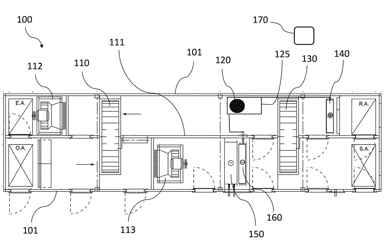
[0008]This invention provides, among other things, various air conditioning units, systems, and methods that control temperature and humidity, for instance, within a space in a building. Various units and systems, for example, include a recovery wheel, a (e.g., passive) dehumidification wheel, a primary cooling coil, a secondary cooling coil, and a heating coil. Further, in various embodiments, a supply airstream passes outdoor air first through the recovery wheel, then through the primary cooling coil, then through the secondary cooling coil, then through the dehumidification wheel, and then to the space. Still further, in many embodiments, an exhaust airstream passes return air from the space first through the heating coil, then through the dehumidification wheel, and then through the recovery wheel.

[0009]Various embodiments provide, for example, as an object or benefit, that they partially or fully address or satisfy one or more of the needs, potential areas for benefit, or oppor...


PUM


Abstract

Air conditioning units, systems, and methods that control temperature and humidity within a space in a building, for example, using a recovery wheel, a desiccant-based or passive dehumidification wheel, a primary cooling coil; and a secondary direct-expansion refrigeration circuit that includes a secondary circuit compressor, a secondary circuit evaporator coil, and a secondary circuit condenser coil. In various embodiments, the system forms a supply airstream that passes outdoor air first through the recovery wheel, then through the primary cooling coil, then through the secondary circuit evaporator coil, then through the dehumidification wheel, and then to the space. Further, in many embodiments, the system forms an exhaust airstream that passes return air from the space first through the secondary circuit condenser coil, then through the dehumidification wheel, and then through the recovery wheel. In some embodiments, various quantities of heat and moisture are transferred between the two airstreams.

Description

RELATED PATENT APPLICATIONS[0001]This U.S. non-provisional patent application claims priority to U.S. Provisional Patent Application Ser. No. 62 / 347,517, filed on Jun. 8, 2016, and has the same title, inventor, and assignee. The contents of the priority provisional patent application are incorporated herein by reference.FIELD OF THE INVENTION[0002]Various embodiments of this invention relate to air conditioning units, systems, and methods that control temperature and humidity, for example, within a space within a building. Many embodiments transfer heat, moisture, or both, from outdoor air in a supply airstream to an exhaust airstream. Certain embodiments relate to air conditioning units, systems, and methods that include or use a recovery wheel, a passive dehumidification wheel, and a cooling coil.BACKGROUND OF THE INVENTION[0003]Heating, ventilating, and air-conditioning (HVAC) systems have been used to maintain desirable temperatures and humidity levels within buildings, and buil...

Claims


Application Information

Patent Timeline
IPC IPC(8): F24F3/147F24F3/14F24F3/153
CPCF24F3/147F24F3/1423F24F2003/1464F24F2203/1032F24F3/153F24F12/002Y02B30/56
Inventor FISCHER, JOHN C.
Owner SEMCO INC
Why Eureka
Try Eureka