Tool and cutting insert for the fine turning of grooves in workpieces

a technology of rotating symmetry and cutting inserts, which is applied in the direction of cutting inserts, manufacturing tools, shaping cutters, etc., can solve the problems of no attractive alternative, loss of cutting edge precision, and complex removal of worn out cutting inserts, so as to prevent angular displacement of inserts

Active Publication Date: 2006-06-20
SANDVIK INTELLECTUAL PROPERTY AB +1
View PDF19 Cites 18 Cited by
  • Summary
  • Abstract
  • Description
  • Claims
  • Application Information

AI Technical Summary

Benefits of technology

[0017]The present invention aims at obviating the above-mentioned problems and at providing an improved tool as well as an improved cutting insert for the tine turning of grooves of the type in question. Therefore, a primary object of the invention is to provide a tool that enables fine turning of the hollow spaces of the grooves in such a way that the internal surfaces of the hollow space become smooth and precise with the purpose of eliminating or reducing the need for after-treatment. It is also an object to provide a tool by means of which the risk of chip stopping in the hollow spaces is obviated. An additional object is to provide a tool that enables a considerable reduction of the number of machining steps between the first and the last machining step. An additional object of the invention is to provide a tool that can be mounted and dismounted with minimal set-up times.SUMMARY OF THE INVENTION
[0019]The invention also involves a cutting insert comprising a top side, a bottom side and a peripheral clearance surface extending between the top and bottom sides. A hole extends from the top side to the bottom side for receiving a fastener. The top side has first and second spaced apart convexly arch-shaped cutting edges. The bottom side includes stabilizing structure arranged for preventing angular displacement of the insert about an axis of the hole.

Problems solved by technology

This means, among other things, that the removal of a worn out cutting insert becomes intricate.
Alternatively, the cutting insert connected by soldering can partially be reground after wearing down of the cutting edge, but this is no attractive alternative because the precision of the cutting edge then is lost as a consequence of the profile of the cutting edge being reduced by the regrinding.
Thus, in the previously known fine turning tools chip stopping may easily arise, if the operator does not help to guide the chip out of the groove above all when one half of the chip profile already has been formed.
Such chip stopping represents an obvious risk that the machined surfaces are scratched.
These may in turn sooner or later give rise to crack formations in the material when the completed product rotates during operation.
In, for instance, coils to jet engines, tendencies to crack formation in the material may become disastrous because the stresses on a coil with fan blades usually are extreme.
Such after-treatment is, however, exceptionally time-consuming and cost-demanding.
Another problem in fine turning by means of previously known turning tools is that the machined surfaces tend to become wavy.
A probable reason for this is that the basic body of the tool, i.e. the long narrow shaft, is comparatively weak, whereby the cutting insert is not kept fixed in an exactly desired position, in particular when the tool is exposed to large cutting forces, something that is the case when the hollow spaces of the grooves are rough and deeply countersunk.
An additional problem of the known fine turning technique is that the tools demand long set-up times and require the lifting of a plurality of heavy complete tool carriers, and in addition to which the cutting inserts must be adjusted and fixed in desired positions.
This problem becomes particularly marked because the fine turning operation demands extremely many (in certain cases 14 or more) different tools having different, successively increasing sizes, which have to be individually set and be fixed as the machining operation proceeds.

Method used


Image

  • Tool and cutting insert for the fine turning of grooves in workpieces
  • Tool and cutting insert for the fine turning of grooves in workpieces
  • Tool and cutting insert for the fine turning of grooves in workpieces

Examples


Embodiment Construction

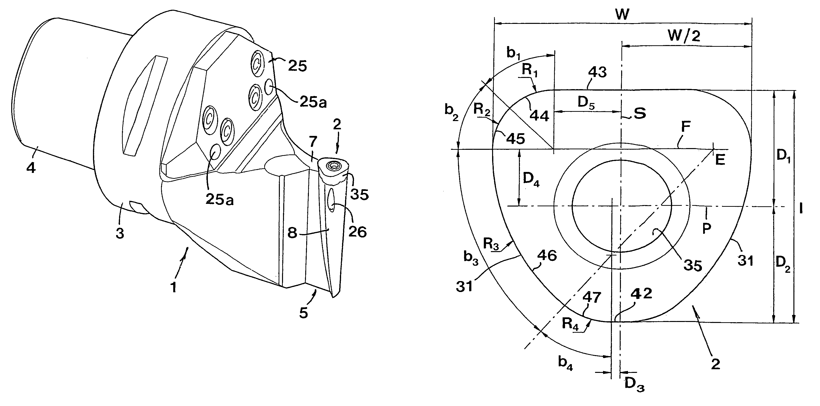
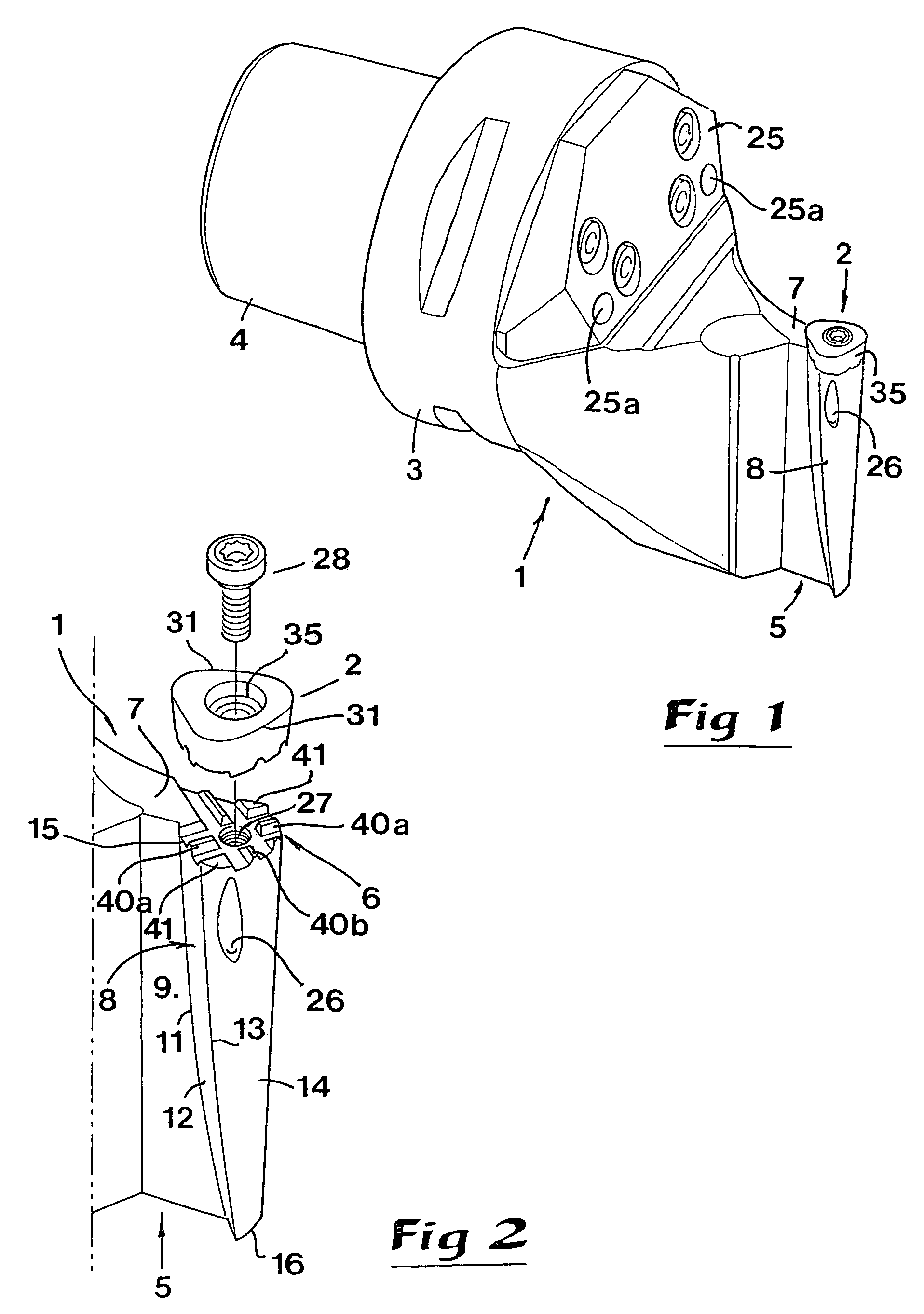
[0035]In FIGS. 1 and 2, a tool is shown in the form of a turning tool, which comprises a basic body 1 and a cutting insert 2, which is detachably mounted on the basic body. In the example, the basic body 1 includes a cylindrical main part 3 from the back side of which a coupling element 4 extends, which can be fixed in a machine tool (not shown). In the front, the basic body has a bracket 5 having a cutting seat 6 in which the cutting insert 2 can be fixed. Said bracket includes a narrow neck part 7 and a support part 8 protruding laterally from the same.

[0036]The cutting insert 2 will be described more in detail later with reference being made to FIGS. 7–10.

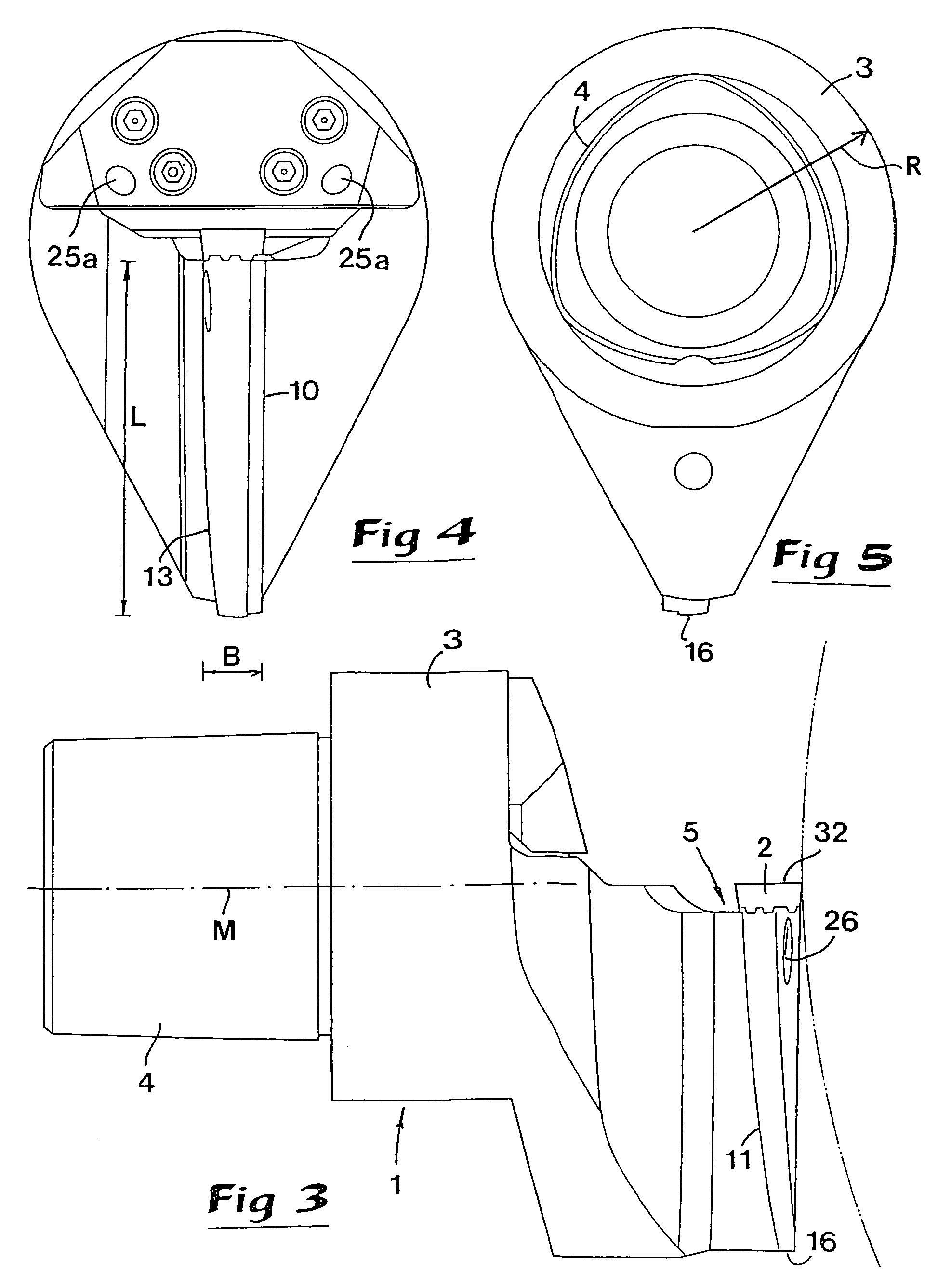
[0037]Now reference is also made to FIGS. 3–6, which together with FIGS. 1 and 2 illustrate the design of the bracket 5 in detail. In FIG. 6 is seen how the comparatively thin neck part 7 is delimited by two planar, opposite side surfaces 9, 10, which advantageously are mutually parallel. The support part 8 projects only from on...


PUM

PropertyMeasurementUnit
obtuse angleaaaaaaaaaa
temperatureaaaaaaaaaa

Abstract

A tool for the fine-turning of grooves in workpieces including a basic body having a rearwardly extending mounting part, and a forwardly projecting bracket. The bracket includes a narrow neck part and an enlarged support part disposed at an end of the neck part. The support part, which forms an insert seat, extends laterally from the neck part wherein the seat is arranged asymmetrically with respect to an imaginary center line of the basic body. A cutting insert includes a bottom side supported on the insert seat. The insert includes two spaced apart convexly arched side cutting edges arranged so that the imaginary center line passes therebetween. A hole is provided through the insert for receiving a fastening screw. The bottom side and the insert seat include mutually engaging stabilizing structures preventing angular displacement of the insert about an axis of the hole.

Description

[0001]This application claims priority under 35 U.S.C. §§ 119 and / or 365 to Patent Application Serial No. 0300696-2 filed in Sweden on Mar. 14, 2003, the entire content of which is hereby incorporated by reference.[0002]1. Technical Field of the Invention[0003]In a first aspect, this invention relates to a tool for the fine turning of rotationally symmetrical grooves in workpieces comprising a basic body and a cutting insert, which is delimited by a top side, a bottom side and at least one clearance surface between the same, and which can be fixed in a cutting seat disposed on a bracket included in the basic body. The bracket includes a narrow neck tart and a support part protruding laterally from the same with the purpose of supporting a portion of the cutting insert protruding laterally in relation to the neck part. That enables, in a workpiece, the turning of internal shoulder surfaces of a hollow space countersunk inside a narrow gap of a groove and having a greater width than t...

Claims


Application Information

Patent Timeline
Patent Type & Authority Patents(United States)
IPC IPC(8): B23B27/16B23B27/06B23B27/10
CPCB23B27/06B23B27/10B23B2200/161Y10T407/2274B23B2220/12Y10T407/23Y10T407/14B23B2205/12
Inventor HESSMAN, INGEMARLUNDBERG, KENNETHLUND, OVEPETERSSON, CARL-GORANWRETLAND, ANDERS
Owner SANDVIK INTELLECTUAL PROPERTY AB
Why Eureka
Try Eureka