

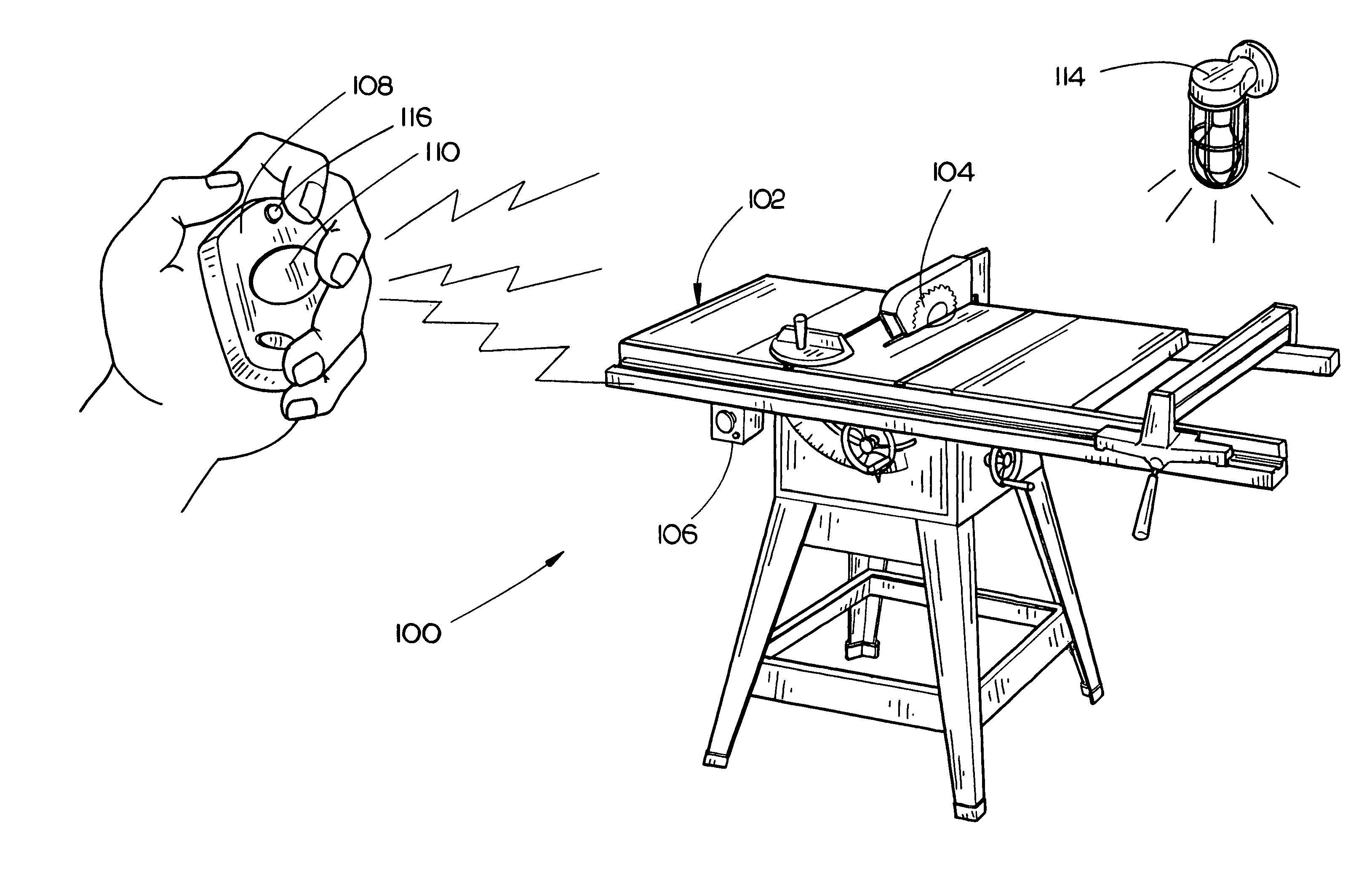
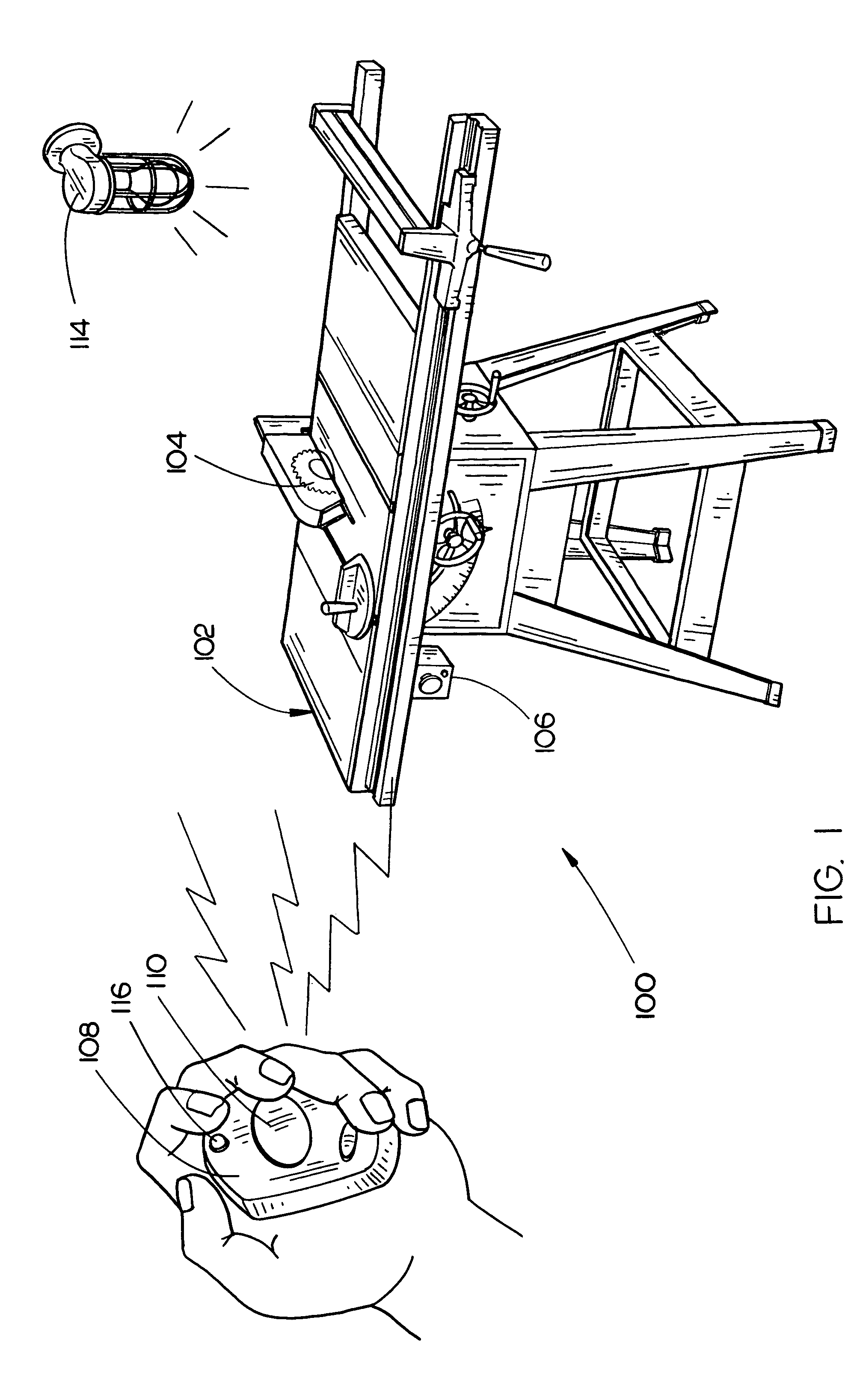
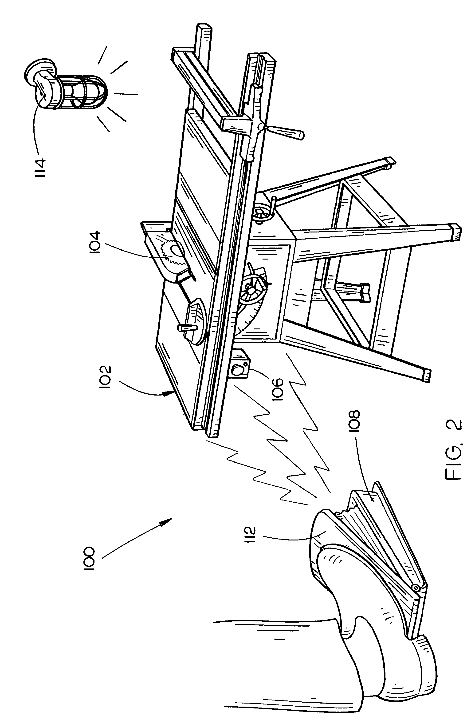
Power tool with remote stop
a technology of power tools and remote stops, which is applied in the direction of position/direction control, metal sawing accessories, starter details, etc., can solve the problem that the placement of such buttons does not allow for remote stopping of a working element of the tool
- Summary
- Abstract
- Description
- Claims
- Application Information
AI Technical Summary
Benefits of technology
Problems solved by technology
Method used
Image

Examples
exemplary embodiment 200
[0024]FIG. 3 illustrates an exemplary embodiment 200 of transmission circuitry for use with a wireless remote stop in accordance with an exemplary embodiment of the present invention. When the button is pressed, switch 202 is activated, and a change of voltage level is presented to a processor 204. In embodiments, a normally closed switch or a normally open switch may be used. Instead of a manually activated switch, a switch may be used which is activated when not substantially oriented in a desired orientation; for example, a switch may be activated when the remote stop 108 is inverted, rapidly accelerated, or the like. The processor 204 may be a Programmable Interrupt Controller (PIC) or other microprocessor. Software code may be downloaded onto the microprocessor to perform the functions of the remote stop 108. The processor 204 provides a signal to the encoder 206 that then provides an encoded signal to the transmitter / antenna 208. Alternatively, an infrared light emitting diode...
exemplary embodiment 300
[0025]FIG. 4 illustrates an exemplary embodiment 300 of reception circuitry for use with a power tool including a wireless remote stop in accordance with an exemplary embodiment of the present invention. An antenna 302 receives a radio frequency signal. In the current embodiment, the antenna is coupled to a receiver module that provides a signal to a decoder 304. The radio frequency signal is decoded by the decoder 304. A processor 306 included in the table saw 102 including the wireless remote stop 108 determines the command associated with the signal. A power cut-off signal may be transmitted directly to a switch 308 to cut off the power supplied to the power tool. Alternatively, the power cut-off command may be latched by a latch that then controls the actuator of the cut off switch. Another switch may determine whether a latched control signal, a momentary signal, or a signal of limited duration is applied to the switch 308. The signal selection made by switch may be set manuall...
PUM
| Property | Measurement | Unit |
|---|---|---|
| power | aaaaa | aaaaa |
| acceleration | aaaaa | aaaaa |
| radio frequency | aaaaa | aaaaa |
Abstract
Description
Claims
Application Information