Charging circuit for parallel charging in multiple battery systems

a charging circuit and multiple battery technology, applied in the direction of charging maintainance, charging/discharging multiple simultaneous batteries, transportation and packaging, etc., can solve the problems of inability to independently ascertain, correct, and most charging circuits for use with multiple batteries do not permit charging multiple batteries in parallel, so as to reduce the system charging parameter

Inactive Publication Date: 2006-06-20
O2 MICRO INT LTD
View PDF15 Cites 45 Cited by
  • Summary
  • Abstract
  • Description
  • Claims
  • Application Information

AI Technical Summary

Benefits of technology

[0006]A method for controlling a system charging parameter provided to a host of batteries, wherein the host of batteries comprises at least a first battery and second battery that may be coupled in parallel is provided. The method consistent with the invention includes: monitoring a first battery charging current level provided to the first battery; monitoring a second battery charging current level provided to the second battery; and reducing the system charging parameter provided to the host of batteries if the first charging current level exceeds a first predetermined maximum charging current level or the second charging current exceeds a second predetermined maximum charging current level.

Problems solved by technology

In addition, such selector circuits typically cannot independently ascertain, correct, and notify other components in the power supply block of a power crises condition.
In addition, such selector circuits are not configured to accept control signals from an associated host power management unit.
Most charging circuits for use with multiple batteries do not permit charging multiple batteries in parallel.

Method used


Image

  • Charging circuit for parallel charging in multiple battery systems
  • Charging circuit for parallel charging in multiple battery systems
  • Charging circuit for parallel charging in multiple battery systems

Examples


Embodiment Construction

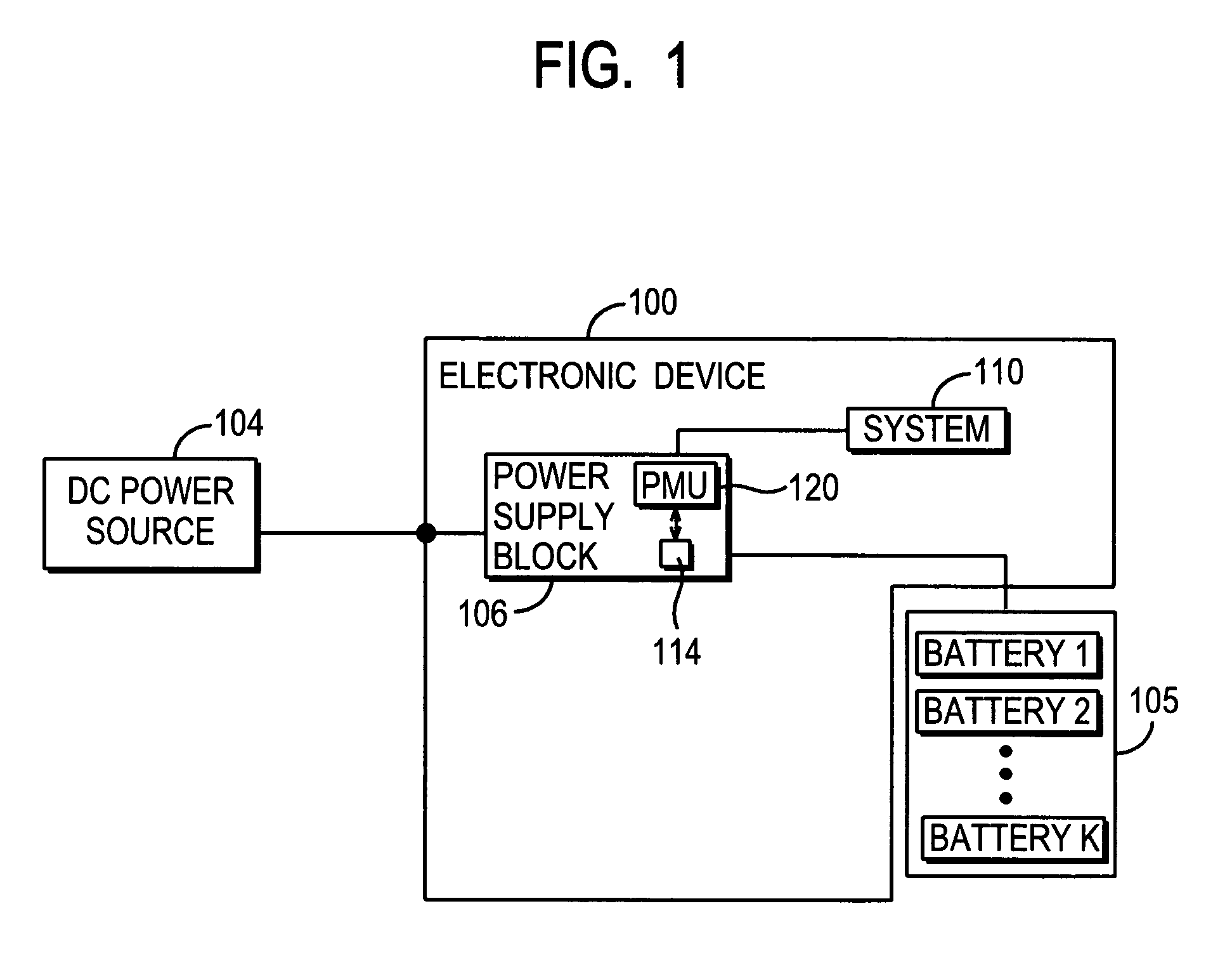
[0020]Turning to FIG. 1, a simplified block diagram of an electronic device 100 capable of being powered from any number of power sources 104, 105 is illustrated. Such power sources may include a plurality of batteries 105 and a DC power source 104. The batteries 105 may further be rechargeable batteries of various types such as lithium-ion, nickel-cadmium, nickel-metal hydride batteries, or the like. The electronic device 100 may be any variety of devices known in the art such as portable electronic devices (laptop computers, cell phones, pagers, personal digital assistants, and the like), an electric powered vehicle, power tools, etc. that may be powered from either power source 104, 105 in various instances.

[0021]If the electronic device 100 is a laptop computer it would include a variety of components known to those skilled in the art which are not illustrated in FIG. 1. For example, the laptop may include an input device for inputting data to the laptop, a central processing un...


PUM


Abstract

A charging circuit for controlling a system charging parameter provided to a host of rechargeable batteries, wherein the host of batteries includes at least a first battery and second battery that may be coupled in parallel. The charging circuit provides for fast charging of rechargeable batteries in parallel. Independent current and voltage sensing for each battery enables parallel charging of batteries at different charging currents. The charging circuit may be configured to accept either analog or digital signals from an associated power management unit.

Description

CROSS REFERENCE TO RELATED APPLICATIONS[0001]The present application is a continuation-in-part application of U.S. Nonprovisional application Ser. No. 10 / 364,228 filed Feb. 11, 2003, the teachings of which are incorporated herein by reference, and claims the benefit of U.S. Provisional Application No. 60 / 457,826 filed Mar. 26, 2003 and U.S. Provisional Application No. 60 / 484,635 filed Jul. 3, 2003, the teachings of both of which are also incorporated herein by reference. The present application is also a continuation-in-part of application Ser. No. 10 / 618,901 filed Jul. 14, 2003 now U.S. Pat. No. 6,861,823, which itself is a continuation of application Ser. No. 10 / 328,466 filed Dec. 23, 2002, now U.S. Pat. No. 6,611,129, which itself is a continuation of application Ser. No. 09 / 948,828 filed Sep. 7, 2001, now U.S. Pat. No. 6,498,461, all of which claim the benefit of Provisional Application Serial No. 60 / 313,260 filed Aug. 17, 2001.FIELD OF THE INVENTION[0002]The present invention r...

Claims


Application Information

Patent Timeline
Patent Type & Authority Patents(United States)
IPC IPC(8): H02J7/00H02J7/02H02J7/10H02J7/34
CPCH02J7/0018H02J7/0019H02J7/0027H02J7/0057H02J7/0068H02J7/34H02J7/022Y02T10/7055H02J2007/0059H02J2007/0067H02M2001/0045H02J7/0069H02J2207/20H02J7/02H02J7/0025Y02T10/70H02M1/0045
Inventor STANESTI, VLAD POPESCUNICULAE, MARIANBUCUR, CONSTANTIN
Owner O2 MICRO INT LTD
Why Eureka
Try Eureka