Antenna device and transmitting/receiving device

a technology of antenna device and transmitting/receiving device, which is applied in the direction of antennas, slot antennas, basic electric elements, etc., can solve the problems of increasing mechanical load on the reciprocal mechanism, increasing manufacturing cost, and increasing the size of the entire antenna apparatus, so as to reduce mechanical load and manufacturing cost, and simplify the structure

Inactive Publication Date: 2006-06-20
MURATA MFG CO LTD
View PDF19 Cites 136 Cited by
  • Summary
  • Abstract
  • Description
  • Claims
  • Application Information

AI Technical Summary

Benefits of technology

[0011]In order to overcome the problems described above, preferred embodiments of the present invention provide an antenna apparatus and a transmitter / receiver capable of reducing a mechanical load as well as manufacturing cost by simplifying a structure.

Problems solved by technology

However, in the antenna apparatus according to the first conventional technique mentioned above, in addition to the necessity for a reciprocal mechanism, such as a linear motor, for reciprocating the primary radiator, etc., it is necessary to accelerate / decelerate the primary radiator, etc., along with the reciprocation of the primary radiator, so that the increased mechanical load on the reciprocal mechanism becomes a problem.
Also, in the second conventional technique, the cam mechanism and the link mechanism required for beam scanning are mechanically complicated, so that the entire antenna apparatus is liable to increase in size, and the layout of the entire antenna apparatus is complicated because of the arrangement of the cam mechanism, thereby increasing manufacturing cost.
However, since the direction of the primary radiator is not directly changed, the dielectric cylinder tends to increase in size.
Hence, there arises a problem in that the load on a motor or the like for rotating the dielectric cylinder is increased, thereby reducing reliability and durability.

Method used


Image

  • Antenna device and transmitting/receiving device
  • Antenna device and transmitting/receiving device
  • Antenna device and transmitting/receiving device

Examples


Embodiment Construction

[0055]An antenna apparatus and a transmitter / receiver according to a preferred embodiment of the present invention will be described below in detail with reference to the attached drawings.

[0056]First, FIGS. 1 to 8 show the antenna apparatus according to a first preferred embodiment and its various frequency characteristics.

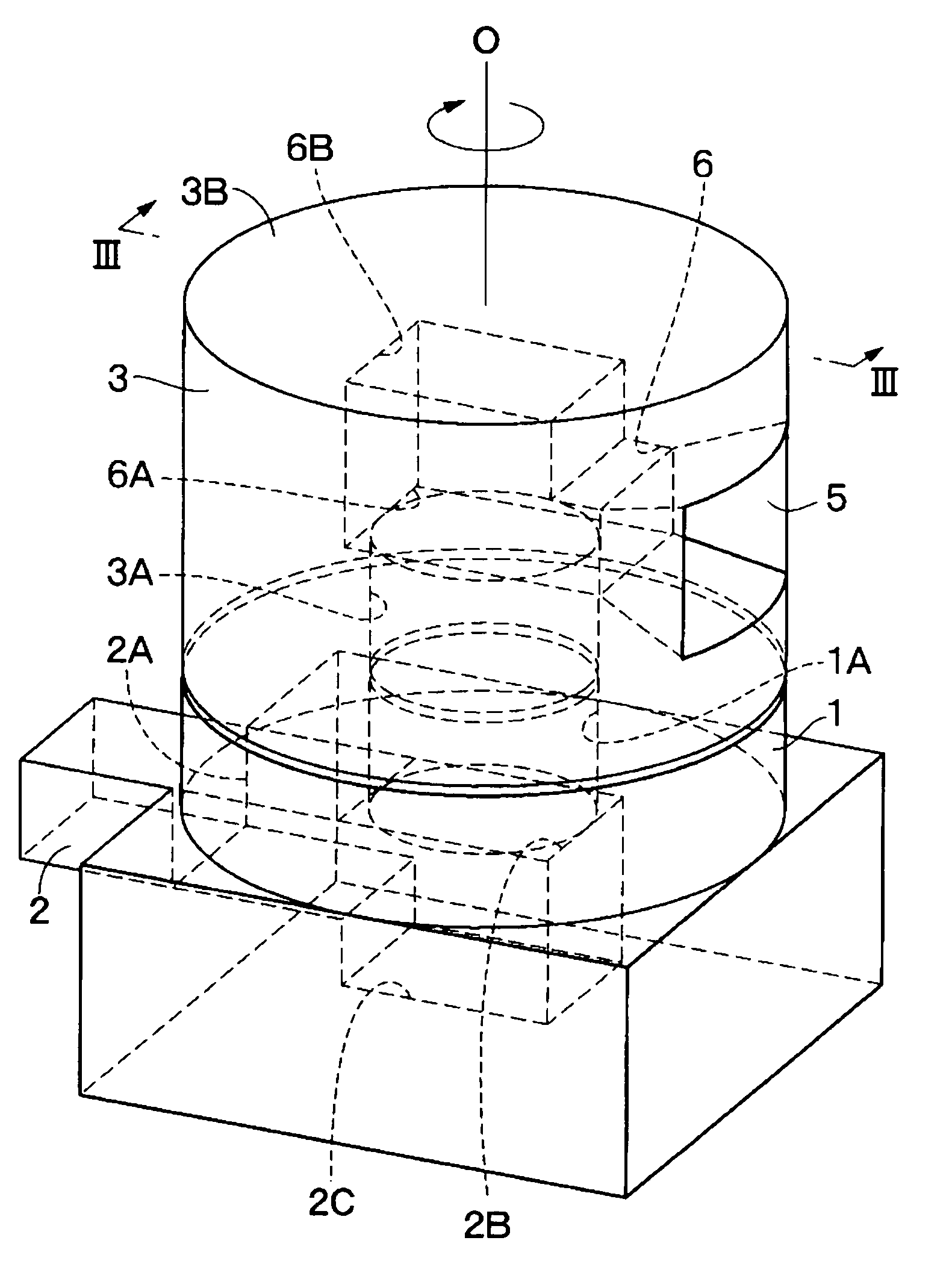
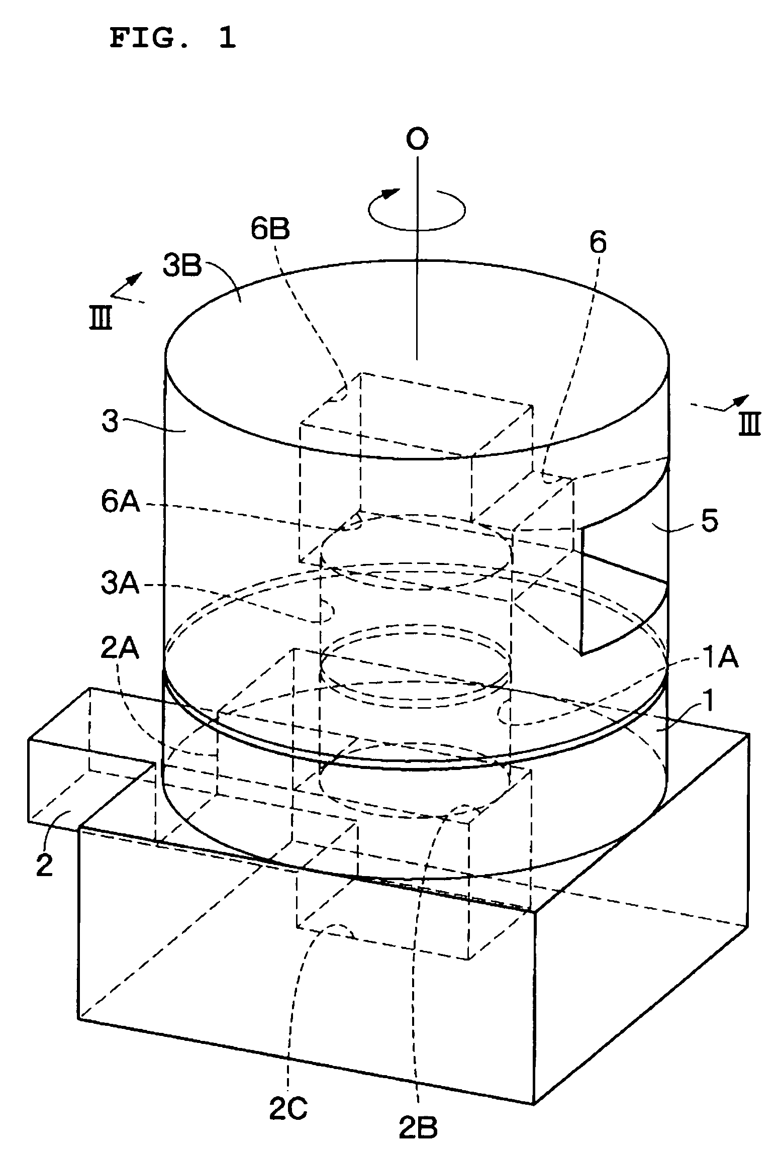
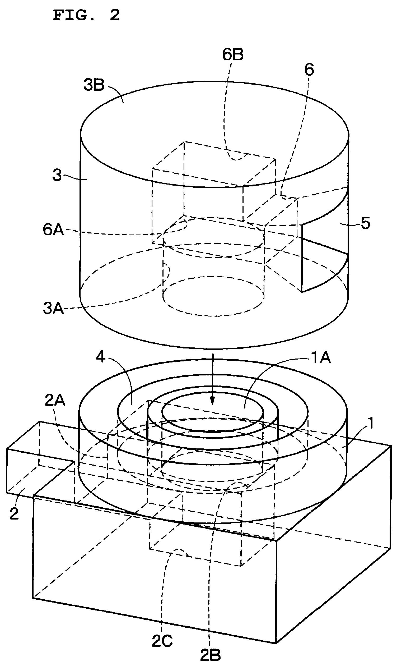
[0057]In the drawings, reference numeral 1 denotes a fixed-side circular waveguide as a cylindrical fixed-side transmission line axially symmetrical about an axis O, and the fixed-side circular waveguide 1 is provided with a circular hole 1A perforated with a circular section and extending in an axial direction. The fixed-side circular waveguide 1 has a propagation mode in a TM01 mode as a magnetic field distribution that is axially symmetrical (rotationally symmetrical) about a transmission direction (axial direction) of high-frequency signals, for example.

[0058]The inner diameter φ of the circular hole 1A herein has a value that allows it to pass through the TM...


PUM


Abstract

An antenna apparatus includes two circular waveguides including a fixed-side circular waveguide and a rotation-side circular waveguide, each having a propagation mode in a TM01 mode, and being arranged coaxially with each other while a waveguide-side choke is provided between the two waveguides. A rectangular waveguide is connected to the fixed-side circular waveguide. Thereby, the high-frequency signal fed from the rectangular waveguide to the fixed-side circular waveguide can be radiated from a primary radiator to which the rotation-side circular waveguide is connected. While the circular waveguides and the waveguide-side choke can constitute a rotary joint, by rotating the primary radiator together with the rotation-side circular waveguide, scanning can be carried out with a high-frequency signal radiated from the primary radiator.

Description

[0001]This application is a 371 of PCT / JP03 / 10282 filed Aug. 13, 2003.BACKGROUND OF THE INVENTION[0002]1. Field of the Invention[0003]The present invention relates to an antenna apparatus that is suitable for use in scanning with high-frequency electromagnetic waves (high-frequency signals), such as micro waves and millimeter waves, over a predetermined angular range, and a transmitter / receiver, such as a radar and a communication apparatus, including such an antenna apparatus.[0004]2. Description of the Related Art[0005]In general, various kinds of beam-scanning antenna apparatuses used for an on-vehicle radar, for example, are known. For example, a first conventional technique involves the use of a reciprocal first dielectric line and a second fixed dielectric line which constitute a directional coupler, and the first dielectric line has a primary radiator connected to move with the reciprocal first dielectric line (Japanese Unexamined Patent Application Publication No. 2001-21763...

Claims


Application Information

Patent Timeline
Patent Type & Authority Patents(United States)
IPC IPC(8): H01Q13/00H01Q13/10H01P1/06H01Q3/04H01Q13/02H01Q21/20
CPCH01P1/062H01Q13/02H01Q3/04H01Q13/0266
Inventor KITAMORI, NOBUMASANAGAI, TOMOHIRO
Owner MURATA MFG CO LTD
Why Eureka
Try Eureka