
Web twister removal process

a technology of web twister and removal process, which is applied in the field of apparatus for detecting and eliminating twisters, can solve the problems of affecting the quality of the untwisted web, the comparatively high speed of the web, and the large number of deflectors, and the web, where the twister is twisted, is exposed to increased strain by the twisting,

Inactive Publication Date: 2006-06-27
THE PROCTER & GAMBLE COMPANY
View PDF12 Cites 7 Cited by
  • Summary
  • Abstract
  • Description
  • Claims
  • Application Information

AI Technical Summary

Benefits of technology

[0012]upon detection of a twister by the scanner and detection arrangement, a control unit triggers the drive of the rotor so that the guide gap on the inlet side is rotated and the twister is eliminated.
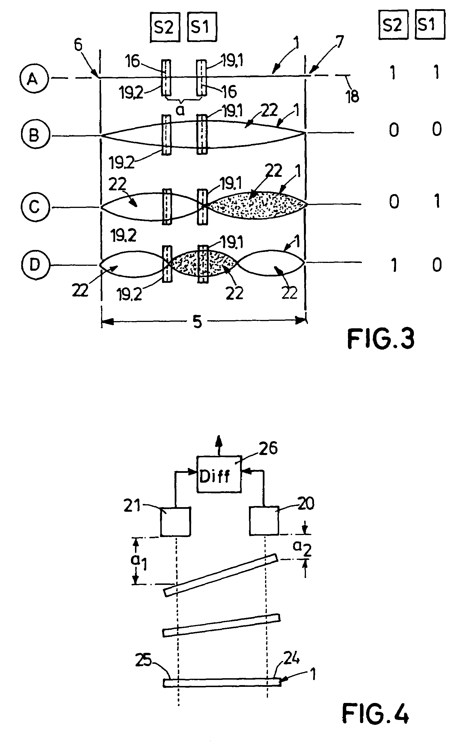
[0015]If two scanner arrangements are disposed at a defined distance along the catch section, the number of twisters that have entered the catch section can be determined—as explained in detail in the exemplary embodiment. In doing so, it can be sufficient only to detect a deflection of the web without recording the extent to which it is deflected and to emit a correspondingly encoded, digital detection signal for further processing in the control unit. It is easily possible to differentiate between numbers ranging from no twister to as many as three twisters.

Problems solved by technology

Problems posed in these manufacturing processes include the comparatively high velocities of the web of several meters per second and the great number of deflectors, conveying rollers and the like for the webs of strip material that frequently have only few centimeters of width.
Problems arise from the fact that, mostly, at least some of the webs of a multilayer product have definitely allocated top and bottom sides.
A twister that has ultimately passed into the assembly operation of the individual webs will lead to a faulty waste product.
Another problem posed by twisters resides in that the web, where twisted, is exposed to increased strain by the twisting.
Furthermore, web guide elements, such as guide gaps, offer some resistance when the twisters pass along, which means additional strain on the web.
In this regard, twisters also cause an increase in web rupturing in the manufacturing plant, meaning standstill, downtime and renewed charging, which considerably affects manufacturing efficiency.

Method used


Image

  • Web twister removal process
  • Web twister removal process
  • Web twister removal process

Examples


Embodiment Construction

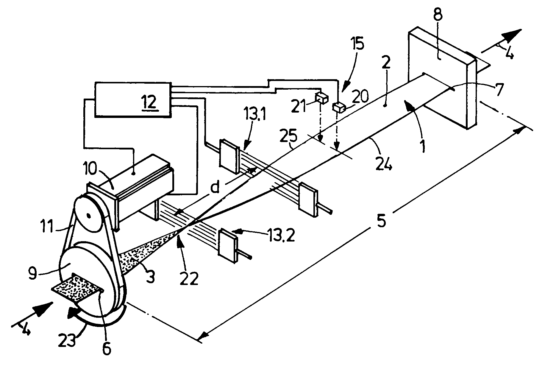
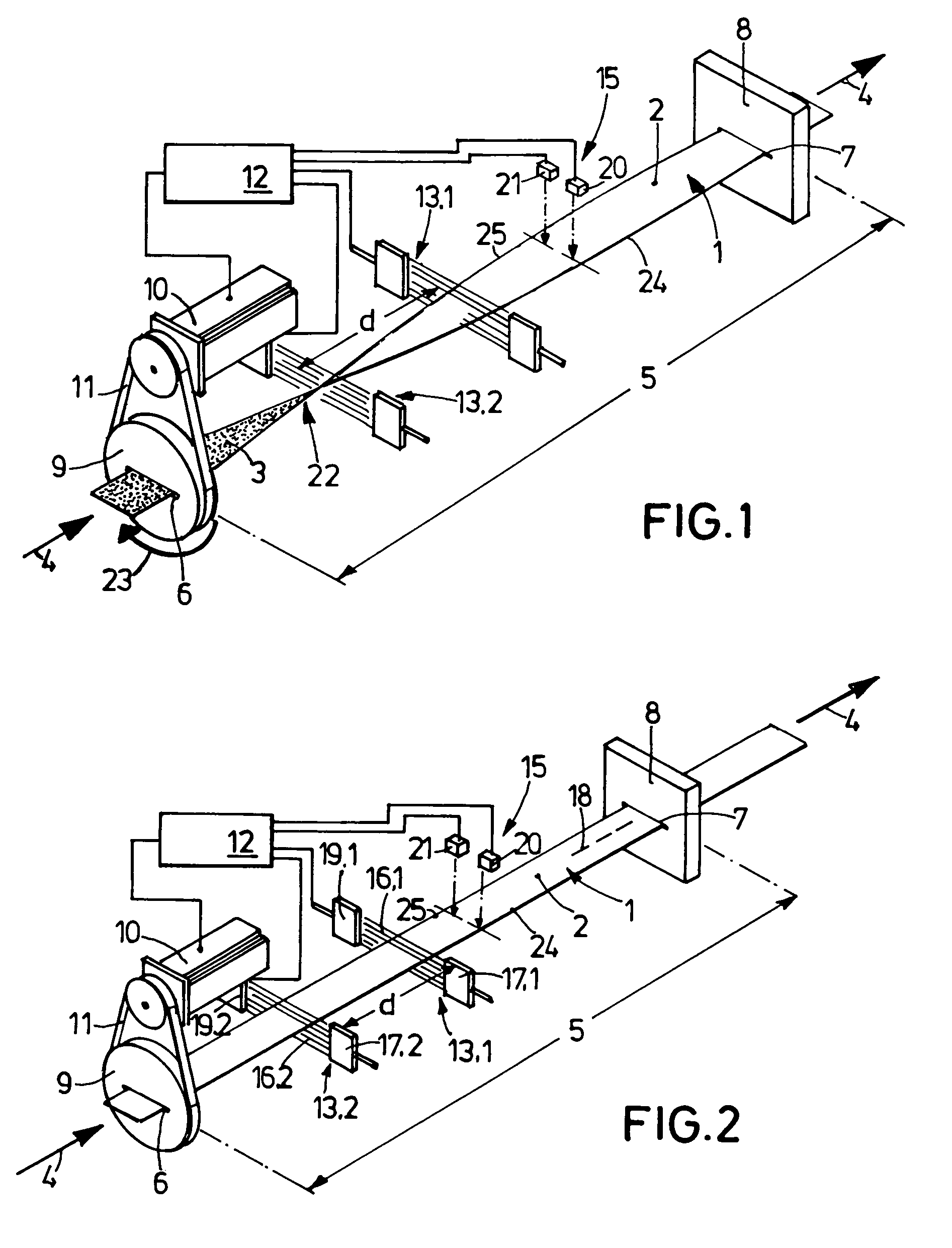
[0021]FIGS. 1 and 2 illustrate the main components of an apparatus for the detection and elimination of twisters in a running web, hereinafter called anti-twister system. Any bearing and mounting elements for the components seen in these figures are omitted for reasons of clarity.

[0022]The two above-mentioned drawings show a web 1 of flexible material such as non-woven fabric. This web 1 has two different surfaces 2, 3, which is symbolized by light and dark coloring of the surfaces in FIGS. 1 and 3. The web 1 passes in the running direction 4 through a catch section 5, which is defined by a gap 6 on the inlet side—hereinafter called inlet gap—and a gap 7 on the outlet side—hereinafter called outlet gap. While the outlet gap 7 is incorporated stationarily in the anti-twister system, which is roughly outlined by the rectangular plate 8 that houses the gap 7, the inlet gap 6 is lodged in a rotor 9 that is mounted rotatably in the anti-twister system. Related to the width and thickness ...


PUM

PropertyMeasurementUnit
flexibleaaaaaaaaaa
distanceaaaaaaaaaa
lengthaaaaaaaaaa

Abstract

An apparatus for detecting and eliminating a twister in a running web of flexible material. The apparatus includes a catch section for twisters, a rotor, a scanner arrangement for detection of a twister that has entered a catch section and a control unit , which, upon detection of a twister by the scanner, triggers the drive of the rotor for untwisting the twister.

Description

FIELD OF THE INVENTION[0001]The invention relates to an apparatus for detecting and eliminating a twister in a running web of flexible material.BACKGROUND[0002]As for the background of the invention, in the manufacture of sanitary articles such as diapers, napkins and pantyliners, various webs of nonwoven fabric and film are wound off supply rolls or bales and combined and united by way of corresponding web guides, with various working operations taking place on the way. Then detachment of individual pieces of the web takes place for configuration of the virtual product.[0003]Problems posed in these manufacturing processes include the comparatively high velocities of the web of several meters per second and the great number of deflectors, conveying rollers and the like for the webs of strip material that frequently have only few centimeters of width. Conditioned by these circumstances, so-called twisters occur as the web winds off and flaps to and fro, in particular in the case of “...

Claims


Application Information

Patent Timeline
Patent Type & Authority Patents(United States)
IPC IPC(8): D02G3/06B65H23/00D06B23/08
CPCB65H23/00D06B23/08B65H2801/57B65H2301/33224
Inventor KRANICH, MARTINLENZ, OLIVER
Owner THE PROCTER & GAMBLE COMPANY
Learn More