Linear actuator

a linear actuator and actuator technology, applied in the direction of dynamo-electric machines, seating furniture, sheet joining, etc., can solve the problems of relatively expensive solution, relatively expensive solution, and large amount of plastic housing in the actuator price, and achieve the effect of simple moulding tools, reduced manufacturing costs, and reduced manufacturing costs

Inactive Publication Date: 2006-06-27
LINAK AS
View PDF26 Cites 72 Cited by
  • Summary
  • Abstract
  • Description
  • Claims
  • Application Information

AI Technical Summary

Benefits of technology

[0009]According to the invention this is achieved by designing the actuator such that the console on the motor housing has an additional fixing for the outer tube, spindle bearing and the rear mounting, and designed to absorb the forces occurring hereon. The console can be designed only with regard to transferring the forces between the bearing and the rear mounting and otherwise made so compact as possible. Accordingly, the motor housing and the console are the supporting parts of the actuator, in other words the chassis. As there are no special demands to the strength of the housing one is freer with regard to the production and the shape of the housing. Therefore the material thickness can be thin, and strengthening ribs can generally be completely avoided which means simpler moulding tools and easier production. Additionally, plastic types of a lower strength can be chosen which is in itself cheaper, but also a production advantage.
[0010]The known actuators are typically assembled with screws, which necessitates the moulding of screw wells and screw towers in the housing and the actual assembly is made manually. As the housing according to the invention is not part of the supporting structure this allows the possibility for the use of other not force transferring methods of assembly. According to an embodiment of the invention the housing is assembled by welding, preferably by ultrasonic welding. This is done by machine, reducing the manual assembly. Additionally, a complete welding makes the housing damp and waterproof, thereby avoiding a labyrinth sealing as with the known actuators. The joining edges can therefore be made more simply and at the same time a manual fitting of a seal is avoided.
[0012]In contrast, according to the invention the housing is two-pieced on a plane determined by the longitudinal axis of the spindle and at a right angle to the motor axle, or generally in this position. This gives assembly advantages, especially when the housing in addition is shaped with a cylindrical section for receiving the motor in an enclosing manner. In this manner the motor is utilized for fixing the housing, preferably with a sound / vibration absorbing layer in between. The housing can additionally be fixed so that it encloses and lies up against the outer tube and rear mounting in the dividing line. Further, the housing can be equipped with internal flanges for additionally fixing of this on the console.
[0017]The known actuators are normally furnished with a fixed cable one end of which via a damp or waterproof is lead in is introduced into the housing. That is to say that one in advance should know the desired length of the cable alternatively furnish the actuators with a standard cable length and then either shorten or extend the cable after demand. In such case it is advantageous to design the housing with a well, which is in connection with a socket inside the actuator. In this manner the actuator can be supplied with the desired length of cable, also the cable is easily exchanged. The plug on the end of the cable can be furnished with an O-ring for damp and waterproof tightening against the side walls of the well.

Problems solved by technology

Such a plastic housing constitutes a considerable amount of the actuators price.
The pressure die cast zinc housing, which must be relatively large because it has to include the motor, makes it a relatively expensive solution.
On the whole a relatively expensive solution.

Method used


Image

  • Linear actuator
  • Linear actuator
  • Linear actuator

Examples


Embodiment Construction

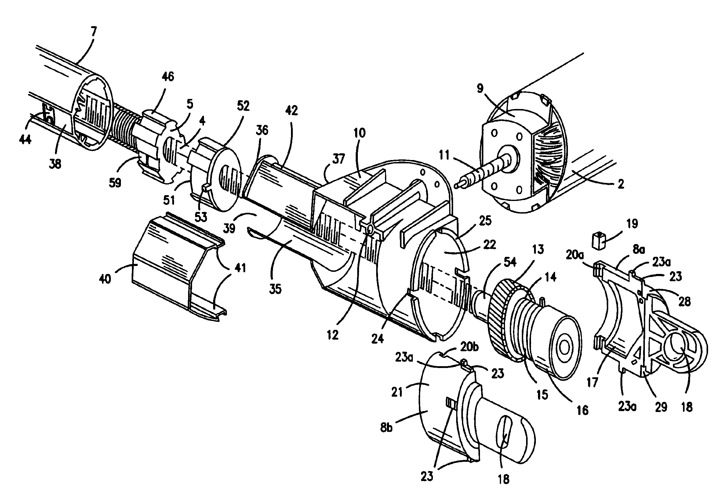
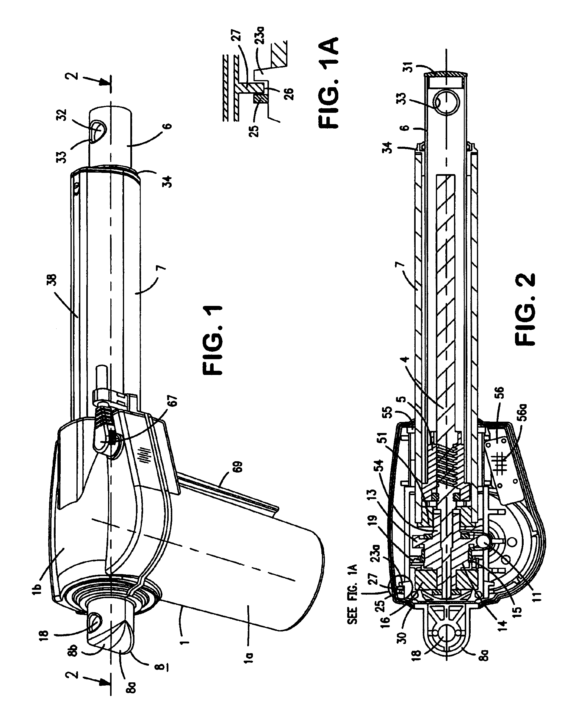
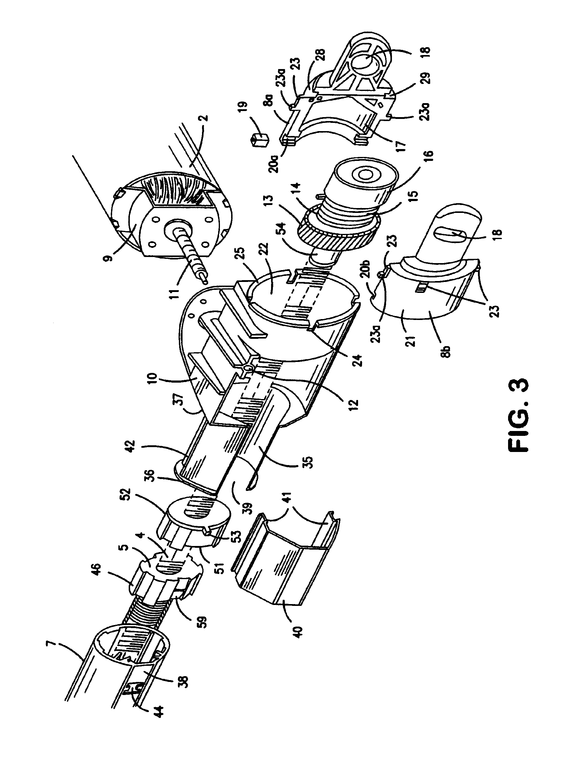
[0034]As shown in the drawings the main parts of the actuator are constituted by a two-piece housing 1, a motor 2 inside a housing part 1a, a worm drive 11, a spindle 4, a spindle nut 5, an activation rod 6, an outer tube 7 and a rear mounting 8.

[0035]The motor 2 is a reversible electric motor, typically a 24V or 48V DC-motor. The motor has a front cover 9, onto which a console 10 is fitted. The motor axle has an extended part formed as a worm 11, the free end of which is bedded in a journal bearing 12 molded in the console.

[0036]At the rear end of the spindle 4, a worm wheel 13 is fitted which engages the worm 11. The worm wheel 13 has on one side a cylindrical element 14 onto which a coil spring 15 rests to increase the self locking ability of the spindle, cf. EP 0 662 573 Linak. Hereafter comes a ball bearing 16 which is held in place, shaping the end of the spindle as a rivet head.

[0037]The ball bearing 16 is encapsulated in a recess 17 in the rear mounting 8, which consisting o...


PUM


Abstract

A linear actuator useful for adjusting furniture includes a housing (1) with a reversible electric-motor (2) which, via a transmission (11, 13), drives a spindle (4) with a force absorbing bearing (16). On the spindle there is a nut (5) to which an actuation rod (86) is fixed surrounded by an outer tube (7). The actuator is with the actuation rod and a rear mounting mounted in the construction into which the actuator should be built-in. The motor housing is part of the supporting construction, as a console is fixed to this (10) with a fixing for the outer tube, spindle bearing and a rear mounting and is designed to absorb the forces occurring hereon. As the housing, as with previously known actuators, need not absorb and transfer forces, this can be made as a thin shell.

Description

BACKGROUND OF THE INVENTION[0001]1. Field of the Invention[0002]The present invention relates to linear actuators.[0003]2. The Prior Art[0004]Linear actuators are for example known from EP 531 247 A1, EP 586 326 A1, EP 647 799 and EP 662 573 A1 all belonging to Linak A / S. The forces occurring on the spindle are absorbed by a push / pull bearing encapsulated in a plastic housing. The forces occurring between the bearing and the rear mounting are transferred through the plastic housing and the housing must be dimensioned and designed accordingly. Such a plastic housing constitutes a considerable amount of the actuators price. From WO 98 / 30816 Linak A / S a sophisticated actuator with a very high performance is disclosed where the forces between the bearing and the rear mounting are transferred via a metal chassis. These actuators are amongst others used in furniture, for example, in hospital and care beds, where is a requirement that the actuators are damp and waterproof. As an example, s...

Claims


Application Information

Patent Timeline
Patent Type & Authority Patents(United States)
IPC IPC(8): F16H27/02F16B5/06A47C20/04A61G7/018F16B5/08F16D13/08F16H1/16F16H25/20F16H25/24H02K7/06H02K7/116
CPCA47C20/041F16H25/20H02K7/06A61G7/018F16H25/2454F16H2025/2084Y10T74/19828F16H2025/2463Y10T74/18576Y10T74/18696Y10T74/18672F16H2025/209F16H2025/2031
Inventor NIELSEN, JENS JORGEN
Owner LINAK AS
Why Eureka
Try Eureka