Output control system for internal combustion engine

a technology of output control system and internal combustion engine, which is applied in electrical control, machines/engines, non-mechanical valves, etc., can solve the problems of difficult to conduct fine control of output, inability to fine control output using cylinder halts, and inability to control output for a smaller number of cylinders

Inactive Publication Date: 2006-06-27
TOYOTA JIDOSHA KK
View PDF13 Cites 128 Cited by
  • Summary
  • Abstract
  • Description
  • Claims
  • Application Information

AI Technical Summary

Benefits of technology

[0015]The present invention was made in order to solve the above problems, and an object of the invention is to provide the output control system of an internal combustion engine that makes it possible, without being limited by the number of cylinders of the internal combustion engine, to implement the fine control of output that uses cylinder halts.

Problems solved by technology

With these techniques, however, the fine control of output that uses cylinder halts is not possible.
This means that the conventional techniques make it difficult to conduct the fine control of output that uses cylinder halts, and make such control of output less feasible for a smaller number of cylinders, in particular.

Method used


Image

  • Output control system for internal combustion engine
  • Output control system for internal combustion engine
  • Output control system for internal combustion engine

Examples


first embodiment

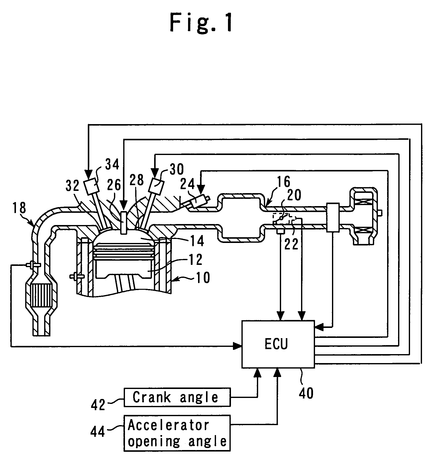
[0027]FIG. 1 is a diagram explaining a configuration of a first embodiment of the present invention.

[0028]The configuration shown in FIG. 1 includes an internal combustion engine 10. The internal combustion engine 10 has a piston 12 in a cylinder. The piston 12 can reciprocate inside the cylinder. Inside the cylinder of the internal combustion engine 10, a combustion chamber 14 is formed above the piston 12. Also, an intake air passageway 16 and an exhaust passageway 18 communicate with the combustion chamber 14.

[0029]A throttle valve 20 is provided in the intake air passageway 16. The throttle valve 20 is an electronic control throttle valve that can control a throttle angle TA independently of an accelerator-opening angle. A throttle sensor 22 that detects throttle angle TA is disposed near the throttle valve 20. A fuel injection valve 24 for injecting fuel into an air intake port of the internal combustion engine 10 is disposed on the downstream side of the throttle valve 20. An ...

second embodiment

[0057]Next, a second embodiment of the present invention is described below with reference to FIGS. 4 and 5.

[0058]A system of the present embodiment is realized according to the system configuration of the first embodiment.

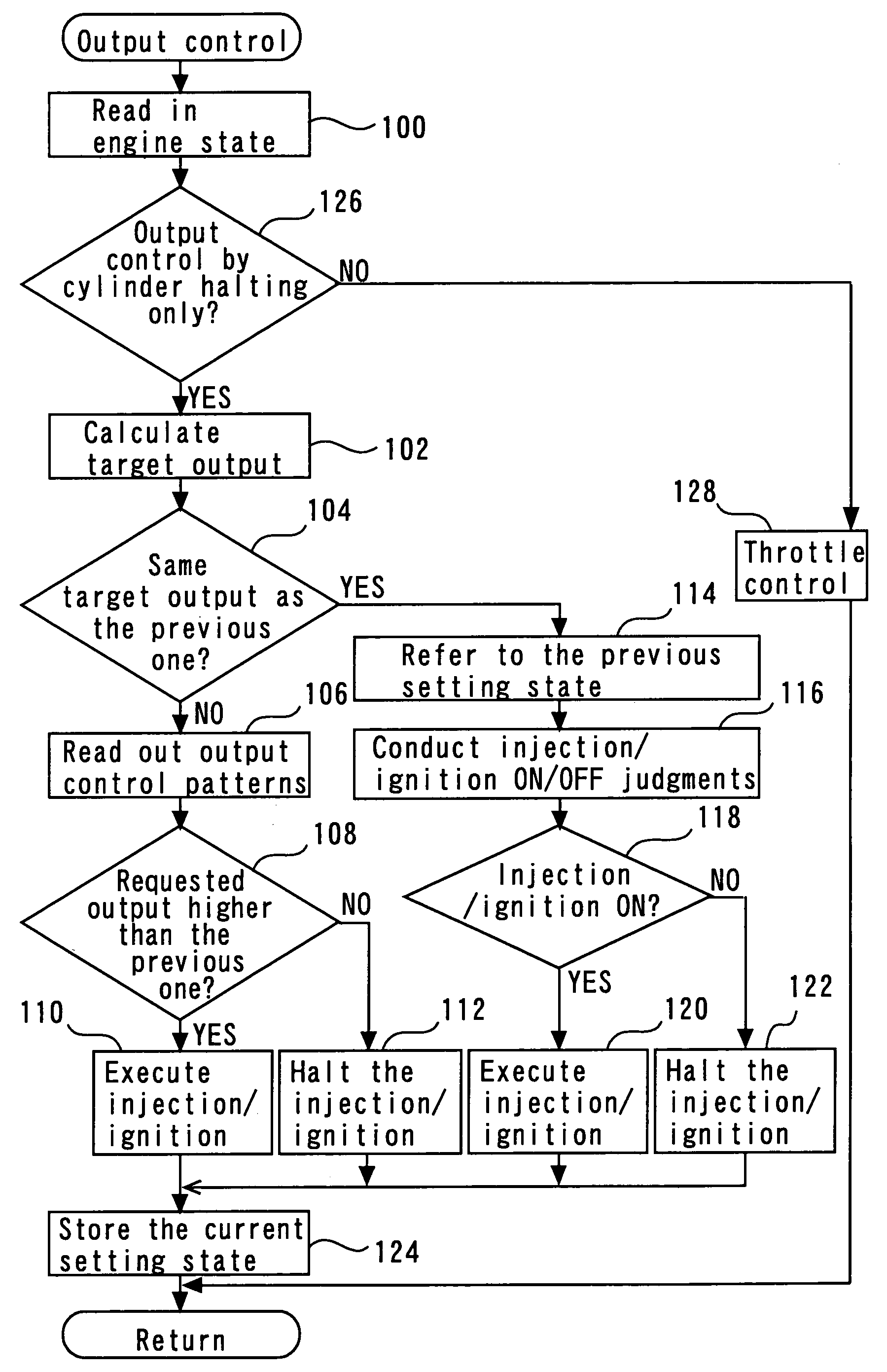
[0059]In an internal combustion engine 10, the number of explosion strokes per unit time increases with an increase in engine speed. Accordingly, when combustion is halted, a combustion halt interval becomes shorter as the engine speed increases. In a high engine speed region, therefore, an increase in the number of combustion halts does not significantly affect drivability. For this reason, in the system of the present embodiment, a region in which output control is conducted only by cylinder halting is changed according to the particular operating state of the internal combustion engine.

[0060]FIG. 4 is a flowchart of the output control routine that the ECU 40 shown in FIG. 1 executes to realize the above function in the second embodiment. In FIG. 4, the same ref...

third embodiment

[0069]Next, a third embodiment of the present invention is described below with reference to FIGS. 6 to 8.

[0070]In a system of the present embodiment, output control based on the same control technique of the first embodiment (the routine of FIG. 3) is realized using the system configuration of the first embodiment.

[0071]The system of the present embodiment is characterized in that in a cylinder whose internal combustion is halted, any pump loss occurring in the halted cylinder is changed (controlled) by changing the valve timing used for that halted cylinder during a period of its internal combustion halt. According to the system of the present embodiment, changing any pump loss occurring in the halted cylinder makes it possible to alleviate any torque fluctuations and vibration occurring in an internal combustion engine 10 during the cylinder halt. Pump loss can also be prevented from occurring in the halted cylinder.

[0072]FIG. 6 is a timing chart showing an example of the valve t...


PUM


Abstract

An intake electromagnetic driving valve and an exhaust electromagnetic driving valve are provided which use electromagnetic force to drive an intake valve and an exhaust valve, respectively. In step 102, the ratio between the number of combustion execution cycles and the number of combustion halts is set to obtain a desired target output value. Output control patterns that each consist of combustion execution timing equivalent to the required number of combustion execution cycles, and combustion halt timing equivalent to the required number of combustion halts are set in step 106, 114. In steps 108 to 112, or 118 to 122, in accordance with the output control patterns, whether combustion is to be executed is set with respect to the explosion timing that arrives in each cylinder in order.

Description

BACKGROUND OF THE INVENTION[0001]1. Field of the Invention[0002]The present invention relates to output control systems of internal combustion engines, and more particularly, to an output control system of an internal combustion engine that controls output by halting internal combustions of cylinders.[0003]2. Background Art[0004]Japanese Patent Laid-open No. 2001-159326, for example, discloses a related technique for halting the combustions inside a part of the cylinders in an internal combustion engine which activates an electromagnetic valve mechanism to control output by controlling the closing timing of intake valves. This technique halts the combustions inside a part of the cylinders in the region where output is not controllable to a target value by controlling the closing timing of intake valves.[0005]Including the above-mentioned document, the applicant is aware of the following documents as a related art of the present invention.[0006][Patent Document 1][0007]Japanese Paten...

Claims


Application Information

Patent Timeline
Patent Type & Authority Patents(United States)
IPC IPC(8): F02D13/06F01L9/04F02D13/02F02D45/00F02D17/02F02D41/04
CPCF02D13/06F02D41/0087F02D13/0253Y02T10/18F02D2041/0012F02D2250/18Y02T10/12
Inventor OGISO, MAKOTO
Owner TOYOTA JIDOSHA KK
Why Eureka
Try Eureka