Casing shoe
- Summary
- Abstract
- Description
- Claims
- Application Information
AI Technical Summary
Benefits of technology
Problems solved by technology
Method used
Image

Examples
first embodiment
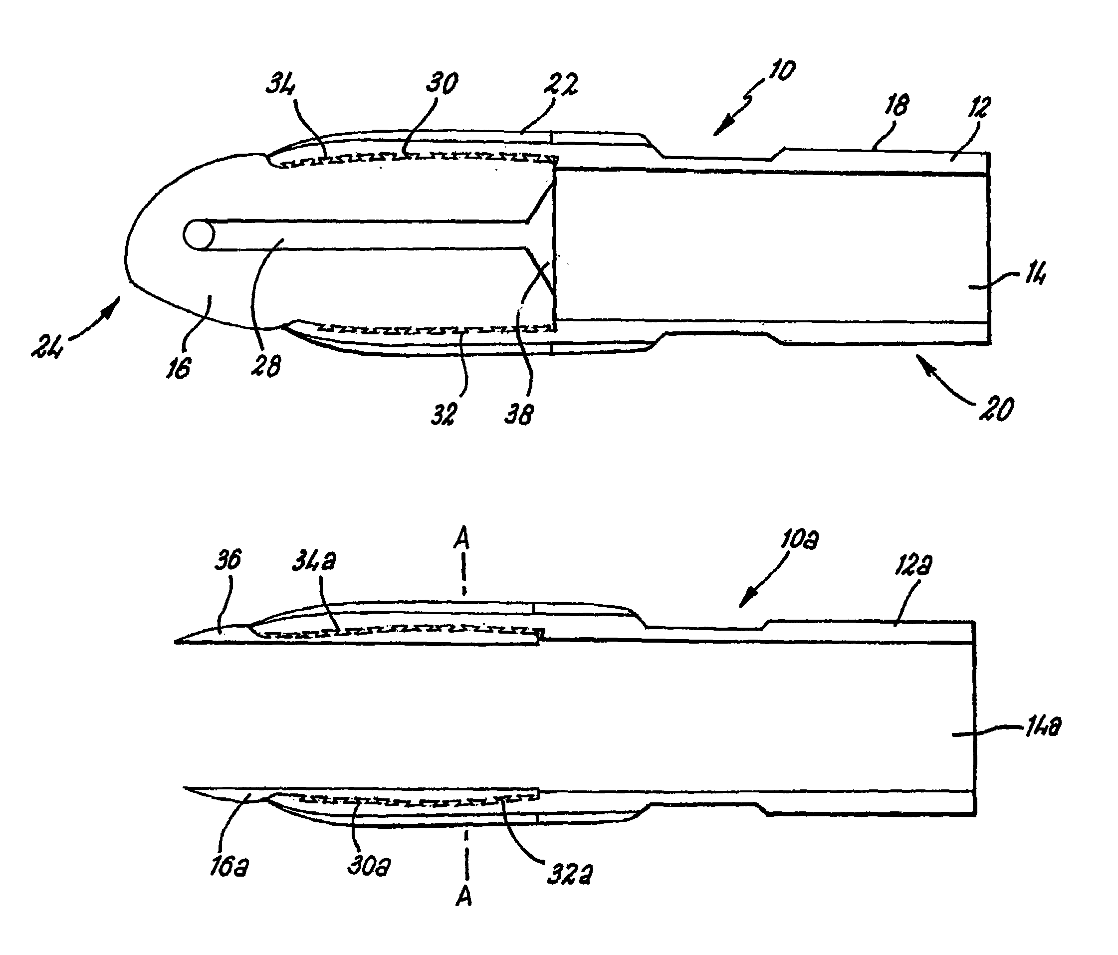
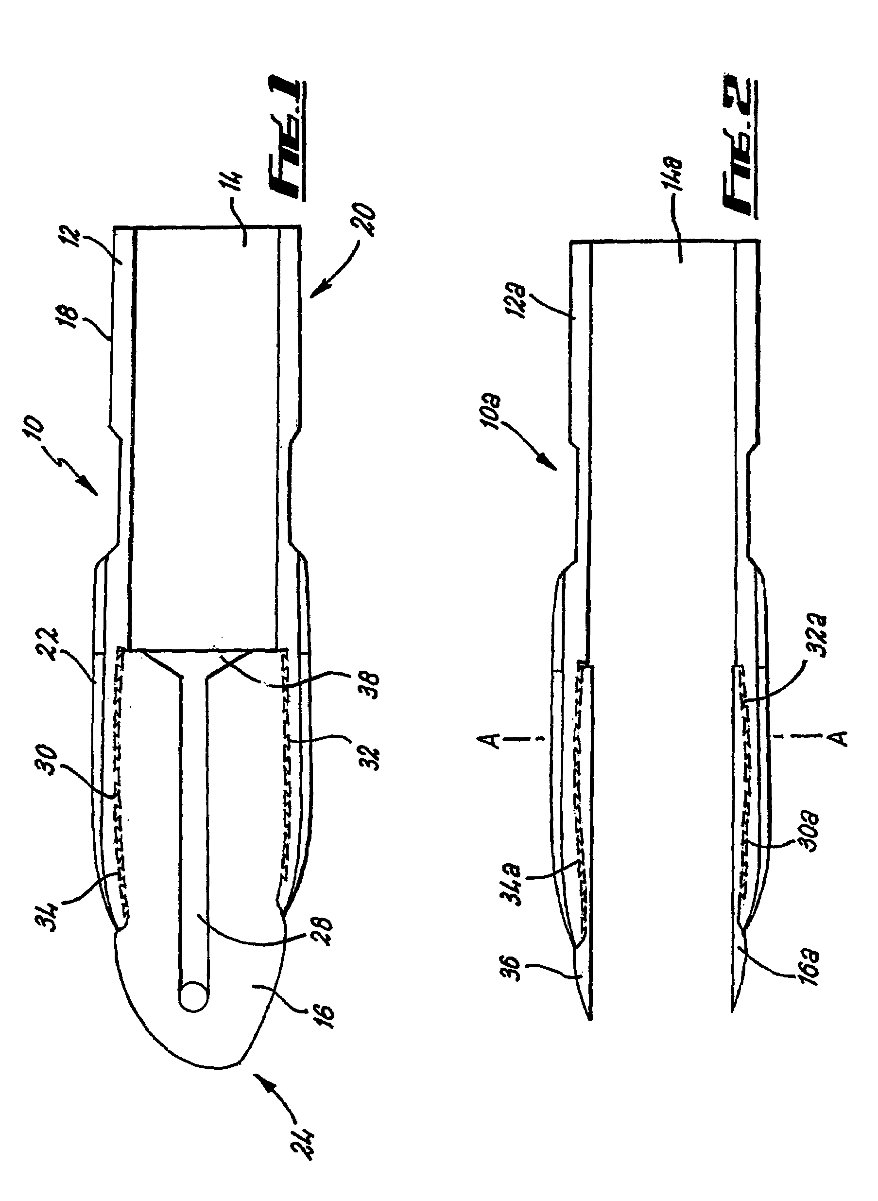
[0032]Reference is first made to FIG. 1 of the drawings which depicts a shoe, generally indicated by reference numeral 10, according to the present invention. The shoe 10 comprises an annular body 12 having a throughbore 14 and a nose portion 16 which is retained within the annular body 12 by an interlocking arrangement 30. The shoe 10 can be mounted on the lower end of a casing string (not shown). Typically mounting is achieved using threaded end connectors 18 located at the rear 20 of the body 10 which mate with the casing.
[0033]The body 12 is a sub and constructed from steel although any relatively hard material would be suitable. The nose portion 16 is of unitary construction from aluminum although any relatively soft material would be suitable.
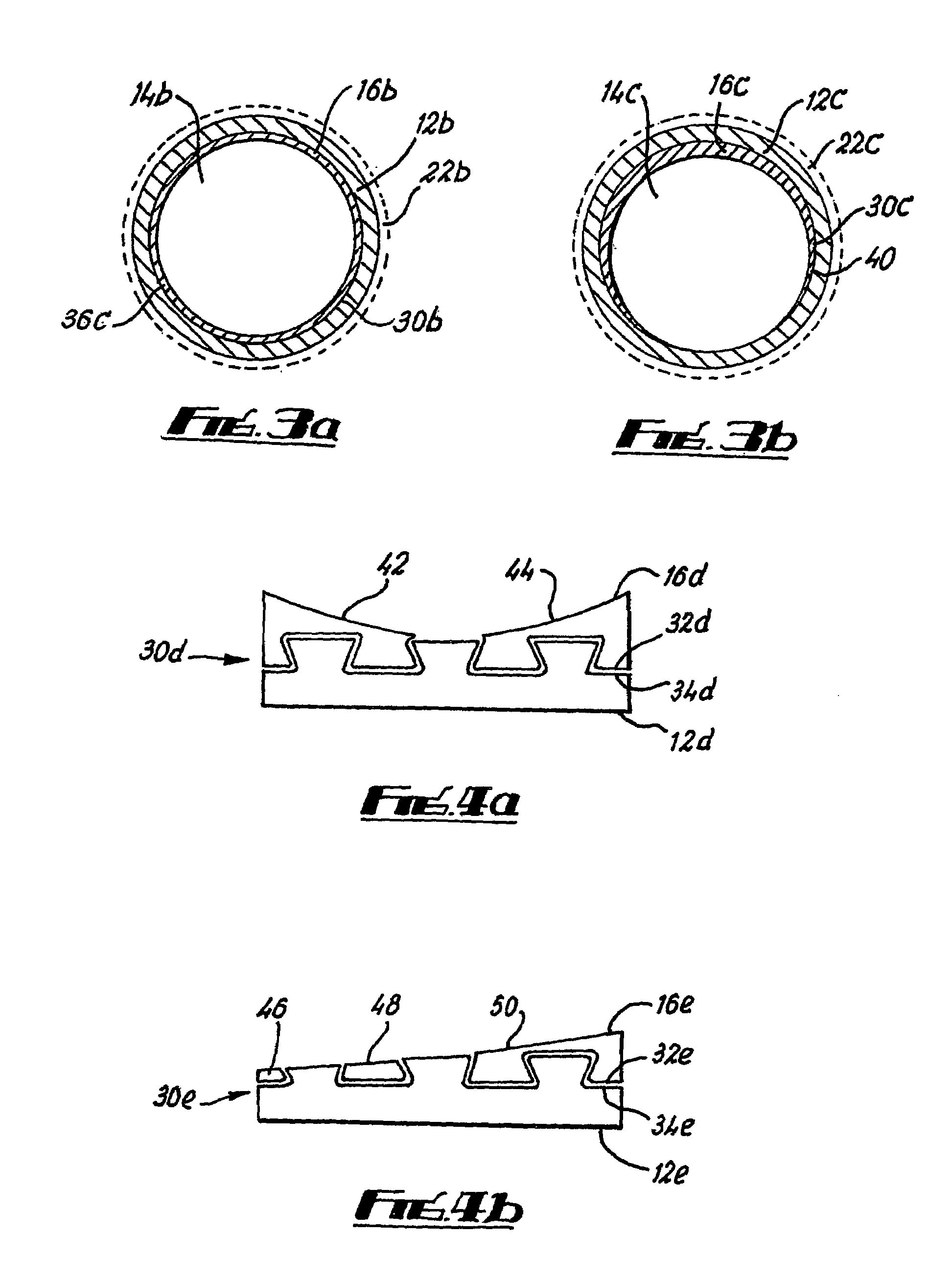
[0034]The body 12 further comprises a reaming portion 22 which supports one or more reaming members. The reaming members are constructed from a hard resistant material such as polycrystalline diamond compact or tungsten carbide, or a comb...
second embodiment
[0043]The nose portion 16f includes cutting elements 52a, b, c. The cutting elements 52a, b, c are arranged on the leading edge of the nose portion 16f to form a drill bit 53, as is known in the art. The cutting elements are made of tungsten carbide. The shoe 10f of the second embodiment may be referred to as a drill bit. In use, the casing 12f is rotated and through the torque the drill bit 53 turns, so drilling a wellbore into which the casing 12f fits. When the casing 12f is in the required position, the nose portion 16f is drilled out as described hereinbefore, with interlocking means 30f positively retaining the remaining sections of the nose portion 16f, so that further shoes may be inserted through bore 14f to extend the wellbore beyond the end of the casing 12f.
third embodiment
[0044]It is known that drilling through tungsten carbide is a difficult process and the present invention, shoe 10g in FIG. 6, illustrates a shoe 10g designed to assist in this. The shoe 10g is similar to the shoe 10 except that the cutting elements 54a, b extend only part way over the face of the nose portion 16g. On FIG. 6, lines C and C′ indicate the section which is removed when the shoe 16g is drilled out.
[0045]Cutting elements 54a, b are arranged to be clear of this section, so that the drilling out procedure does not require drilling through the hard material of the cutting elements 54a, b.
[0046]The principle advantage of the present invention is in the ability of the body to positively retain all or even parts of the nose portion once the drilling out operation is complete so improving the reliability of the shoe.
[0047]It will be appreciated that modifications and improvements may be made to the embodiment hereinbefore described without departing from the scope of the inven...
PUM
 Abstract
Description
Claims
Application Information
 - Generate Ideas
- Intellectual Property
- Life Sciences
- Materials
- Tech Scout
- Unparalleled Data Quality
- Higher Quality Content
- 60% Fewer Hallucinations
Browse by: Latest US Patents, China's latest patents, Technical Efficacy Thesaurus, Application Domain, Technology Topic, Popular Technical Reports.
© 2025 PatSnap. All rights reserved.Legal|Privacy policy|Modern Slavery Act Transparency Statement|Sitemap|About US| Contact US: help@patsnap.com