
Sealing device for water pump bearings

a technology of sealing device and water pump bearing, which is applied in the direction of mechanical equipment, rotary machine parts, machines/engines, etc., can solve the problems of increasing costs, and achieve the effect of excellent sealing performance and convenient operation

Inactive Publication Date: 2006-06-27
KOYO SEIKO CO LTD
View PDF27 Cites 19 Cited by
  • Summary
  • Abstract
  • Description
  • Claims
  • Application Information

AI Technical Summary

Benefits of technology

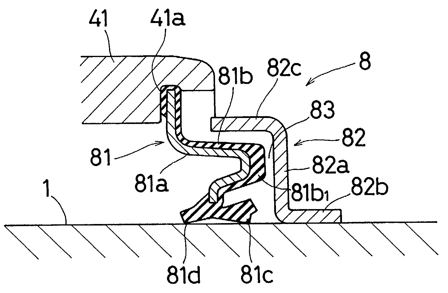
[0012]In the sealing device for a water pump bearing, the economical seal member which is not provided with an axial lip and, which has only a radial lip is fixed to the shoulder portion of the outer race. However, the seal member has a section shape which is bent along the disk portion and the outer cylindrical portion of the slinger, and the labyrinth seal portion is formed between the seal member, and the disk portion and the outer cylindrical portion of the slinger. Although an axial lip is not disposed, therefore, the labyrinth seal portion and the radial lip alone can exhibit sufficient seal performance.
[0013]According to another feature of the sealing device of the invention, the radial lip of the seal member may be in contact with the outer peripheral face of the pump shaft, or placed in close proximity to the outer peripheral face of the pump shaft so as to form the labyrinth seal portion. Alternatively, the radial lip may be in contact with an outer peripheral face of the inner cylindrical portion of the slinger, or placed in close proximity to the outer peripheral face of the inner cylindrical portion of the slinger so as to form the labyrinth seal portion. In both the cases, excellent seal performance is exhibited by the radial lip and the formed labyrinth seal portion.
[0017]In the sealing device for a water pump bearing, the expanded portion disposed in the bent portion of the seal member can increase the distance in the axial direction of the labyrinth seal portion formed between the outer cylindrical portion and the expanded portion, and a process of bending a core constituting the seal member can be easily conducted. In accordance with another feature, the radial lip of the seal member may be in contact with the outer peripheral face of the pump shaft, or placed in close proximity to the outer peripheral face of the pump shaft so as to form the labyrinth seal portion. Alternatively, the radial lip may be in contact with an outer peripheral face of the inner cylindrical portion of the slinger, or placed in close proximity to the outer peripheral face of the inner cylindrical portion of the slinger so as to form the labyrinth seal portion. In both the cases, excellent seal performance is exhibited by the radial lip and the formed labyrinth seal portion.

Problems solved by technology

However, the seal member 51 of the triple lip type configured as described above has a complicated structure because it has the axial lip 51e, thereby producing a problem in that the cost is increased.

Method used


Image

  • Sealing device for water pump bearings
  • Sealing device for water pump bearings
  • Sealing device for water pump bearings

Examples


first embodiment

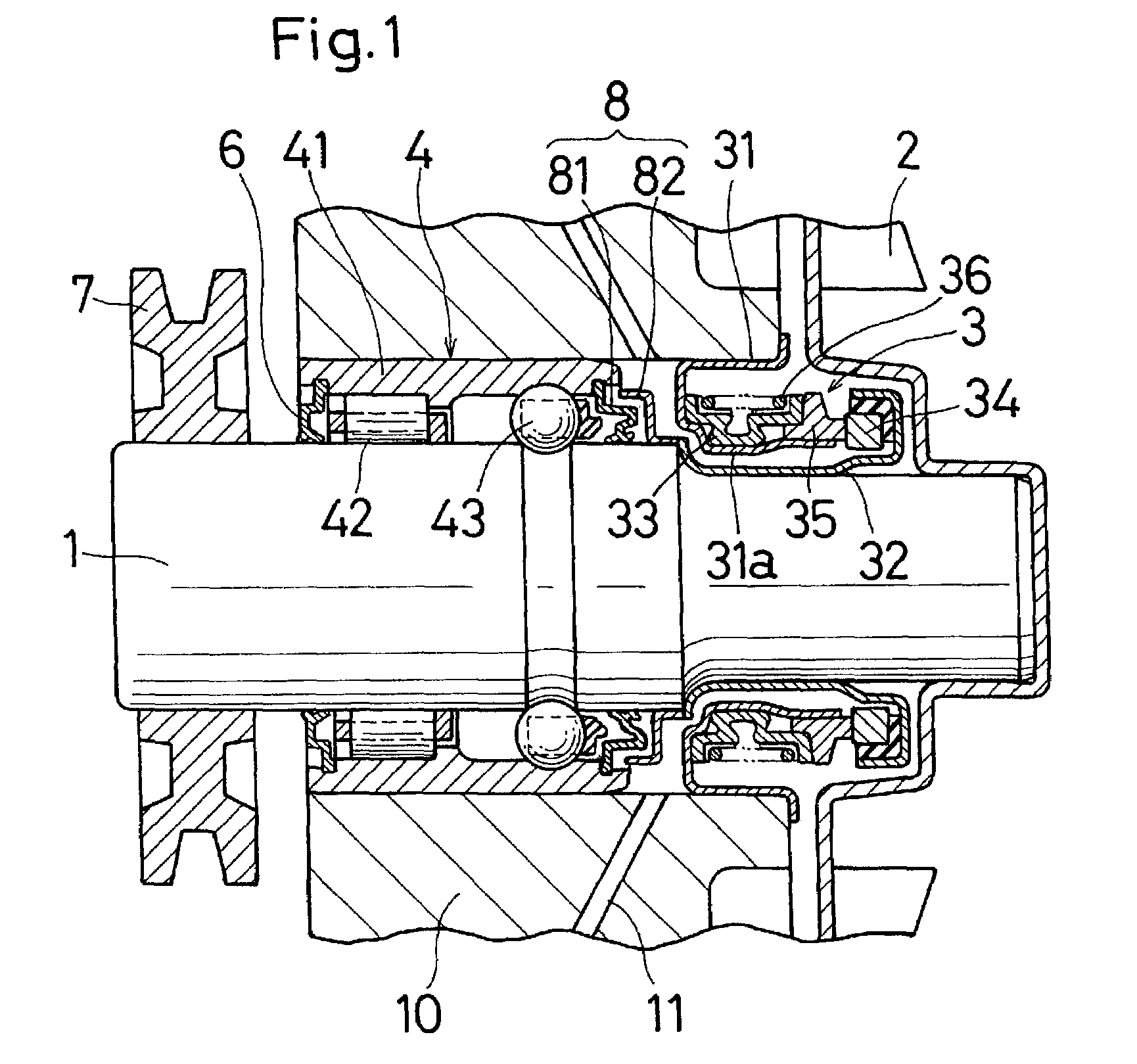
[0029]FIG. 1 is a partial section view showing the structure of a water pump into which a sealing device for a water pump bearing of the invention is incorporated, and FIG. 2 is an enlarged section view of the upper half of the sealing device.

[0030]The water pump has the same structure as the above-described conventional water pump, with the exception of a sealing device 8 of a water pump bearing 4 on the side of the impeller 2, and comprises a pump shaft 1, an impeller 2, a mechanical seal 3, the water pump bearing 4, sealing devices 6 and 8 for the water pump bearing, a pulley 7, etc.

[0031]The pump shaft 1 has a small-diameter portion and a large-diameter portion. The mechanical seal 3 is disposed on the small-diameter portion, and the water pump bearing 4 is disposed on the large-diameter portion. The impeller 2 is attached to one end of the pump shaft 1, and the pulley 7 is attached to the other end. The pump shaft 1 and the impeller 2 are rotated by a belt (a belt which transmi...

second embodiment

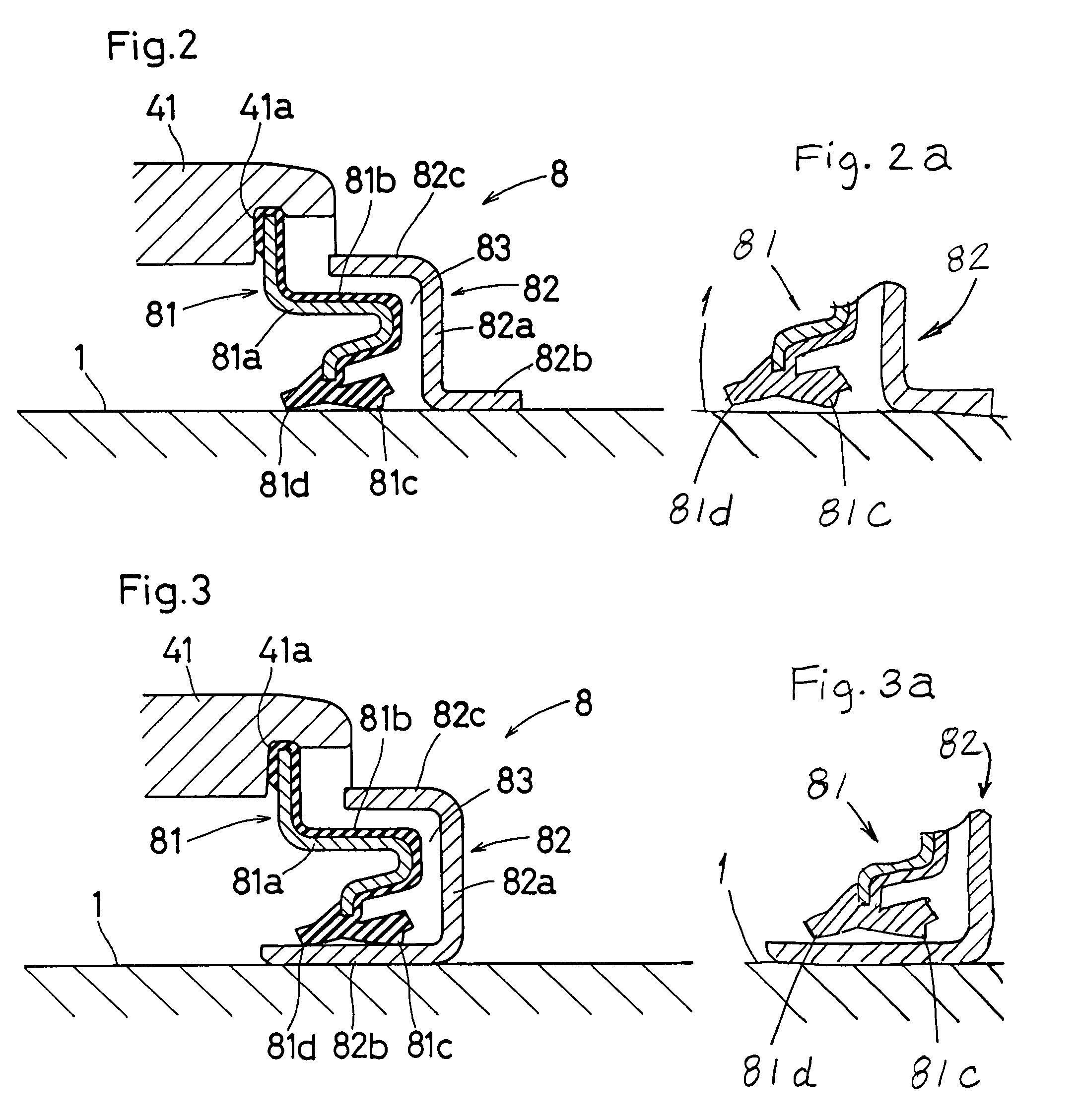
[0039]FIG. 3 is an enlarged section view of the upper half of a sealing device for a water pump bearing of the invention.

[0040]In the slinger 82 of the sealing device 8, the inner cylindrical portion 82b and the outer cylindrical portion 82c are extended from the inner and outer peripheries of the disk portion 82a toward the other end (toward the water pump bearing 4) in the axial direction, respectively, so that the slinger has a substantially U-like section shape. The slinger is configured so that the two radial lips 81c and 81d on the inner periphery of the seal member 81 are in contact with the outer peripheral face of the inner cylindrical portion 82b.

[0041]The other configuration of the sealing device 8 is identical with that of the above-described sealing device. Therefore, the identical components are denoted by the same reference numerals in FIG. 3, and their description is omitted.

[0042]In the thus configured sealing device 8 also, since the economical seal member 81 of t...


PUM


Abstract

A sealing device for a water pump bearing employs a seal member without an axial lip, and having only a radial lip. The sealing device includes an annular seal member which is fixed to a shoulder portion of one end in an axial direction of an outer race of a water pump bearing and an annular slinger which is positioned on a side of the one end in the axial direction with respect to the seal member and externally fixed to the outer peripheral face of a pump shaft serving as an inner race. The seal member has a section shape which is bent along a disk portion and an outer cylindrical portion of the slinger. A labyrinth seal portion is formed between the seal member, and the disk portion and the outer cylindrical portion of the slinger. Radial lips are formed on an inner periphery of the seal member.

Description

BACKGROUND OF THE INVENTION[0001]The present invention relates to a sealing device for a water pump bearing.[0002]For example, a structure such as shown in FIG. 8 is known as a water pump for circulating cooling water in an automobile engine, or the like.[0003]The water pump comprises a pump shaft 1, an impeller 2, a mechanical seal 3, a water pump bearing 4, sealing devices 5 and 6 for the water pump bearing, a pulley 7, etc. The impeller 2 is attached to one end of the pump shaft 1, and the pulley 7 is attached to the other end. The pump shaft 1 and the impeller 2 are rotated by a belt (a belt which transmits rotation of a crankshaft of an engine) which is wound around the pulley 7, so that cooling water in a pump chamber is sent out.[0004]In the water pump bearing 4, the pump shaft 1 is used as an inner race, and an outer race 41 is externally attached to the outer peripheral face of the inner race via a cylindrical roller group 42 and a ball group 43 serving as rolling elements....

Claims


Application Information

Patent Timeline
Patent Type & Authority Patents(United States)
IPC IPC(8): F16J15/32F16J15/447F16C19/49
CPCF16C19/49F16C33/7859F16C33/805F16C2360/44F16C2240/40F16J15/002F16J15/3264F16J15/348F16J15/4476
Inventor SAKATA, YOSHIZUMI
Owner KOYO SEIKO CO LTD
Learn More