Liquid crystal display controller

a liquid crystal display and controller technology, applied in the field of liquid crystal display controllers, can solve the problems of increasing power consumption, difficult to hold the frame frequency constant without limitations on the number of active lines, and image quality may deteriorate, so as to achieve low power consumption, good display quality, and low power consumption

Inactive Publication Date: 2006-06-27
SYNAPTICS JAPAN GK
View PDF15 Cites 24 Cited by
  • Summary
  • Abstract
  • Description
  • Claims
  • Application Information

AI Technical Summary

Benefits of technology

[0010]The present invention provides a liquid crystal display controller device and method which provides for a full and / or partial display with good display quality and / or low power consumption based on the scanning period for an active scan line being dependent upon a number of reference clock pulses. Some embodiments of the present invention include one or more of the following features: keeping the frequency substantially constant for different numbers of active scan lines, allowing change of the frequency due to characteristics of the LCD, displaying gradation with near linear effective voltage characteristics, displaying graduation data with lower power, or displaying a partial or full screen in a mobile device, for example, a cell phone.
[0011]In the liquid crystal display controller according to a first embodiment of the present invention, a register is provided to preset the original clock division ratio and the number of clocks for one scanning period and preset data can be entered into the register from outside. This makes it possible to hold the frame frequency almost constant with different numbers of active lines and to change the frame frequency easily.
[0012]In the liquid crystal display controller according to a second embodiment of the present invention, when a PWM-based gradation display function is provided, one scanning period is divided into an effective period and an ineffective period, where the data voltage with a suitable time length for display data and a selected voltage level for scanning signals are given during the effective period only. This makes it possible to obtain linear effective voltage characteristics with respect to gradation display data even when the number of clocks for one scanning period is varied.
[0013]The liquid crystal display controller according to a third embodiment of the present invention provides various data signal waveforms for PWM to realize power consumption reduction and high display image quality.
[0014]The liquid crystal display controller according to a forth embodiment of the present invention is used in a cellular phone system. Even if display data for a desired part of the screen changes during standby, a high quality image is provided with low power consumption.

Problems solved by technology

As a result, the image quality may deteriorate, for example, shadowing may occur.
However, the number of lines for a partial display to hold the frame frequency constant is limited to ½, ¼, ⅛ and so on of that for the full screen display; therefore it is difficult to hold the frame frequency constant without limitations on the number of active lines.
For example, if a liquid crystal with quick brightness response is used, generally the frame frequency must be increased to obtain a satisfactory contrast, though a higher frame frequency leads to an increase in power consumption.
However, conventional liquid crystal display controllers are not designed to change the frame frequency depending on the operating mode of the liquid crystal display unit.

Method used


Image

  • Liquid crystal display controller
  • Liquid crystal display controller
  • Liquid crystal display controller

Examples


second embodiment

[0062]Next, referring to FIGS. 6 to 13, the present invention will be detailed.

[0063]A liquid crystal display controller according to the second embodiment of the present invention enables gradation displays.

[0064]PWM (pulse width modulation) is used as the gradation display method. In the PWM method, as shown in FIG. 6, regarding the data signals given to data lines on the liquid crystal panel, one scanning period is divided into two or more periods, e.g., 610, 612 and 614, and ON or OFF voltage is given to each divisional period, where the ratio of ON voltage to OFF voltage is determined by the gradation information included in the display data 616 (hereinafter referred to as gradation display data), so that intermediate display brightness can be obtained, e.g., 620, 622, 624, and 626.

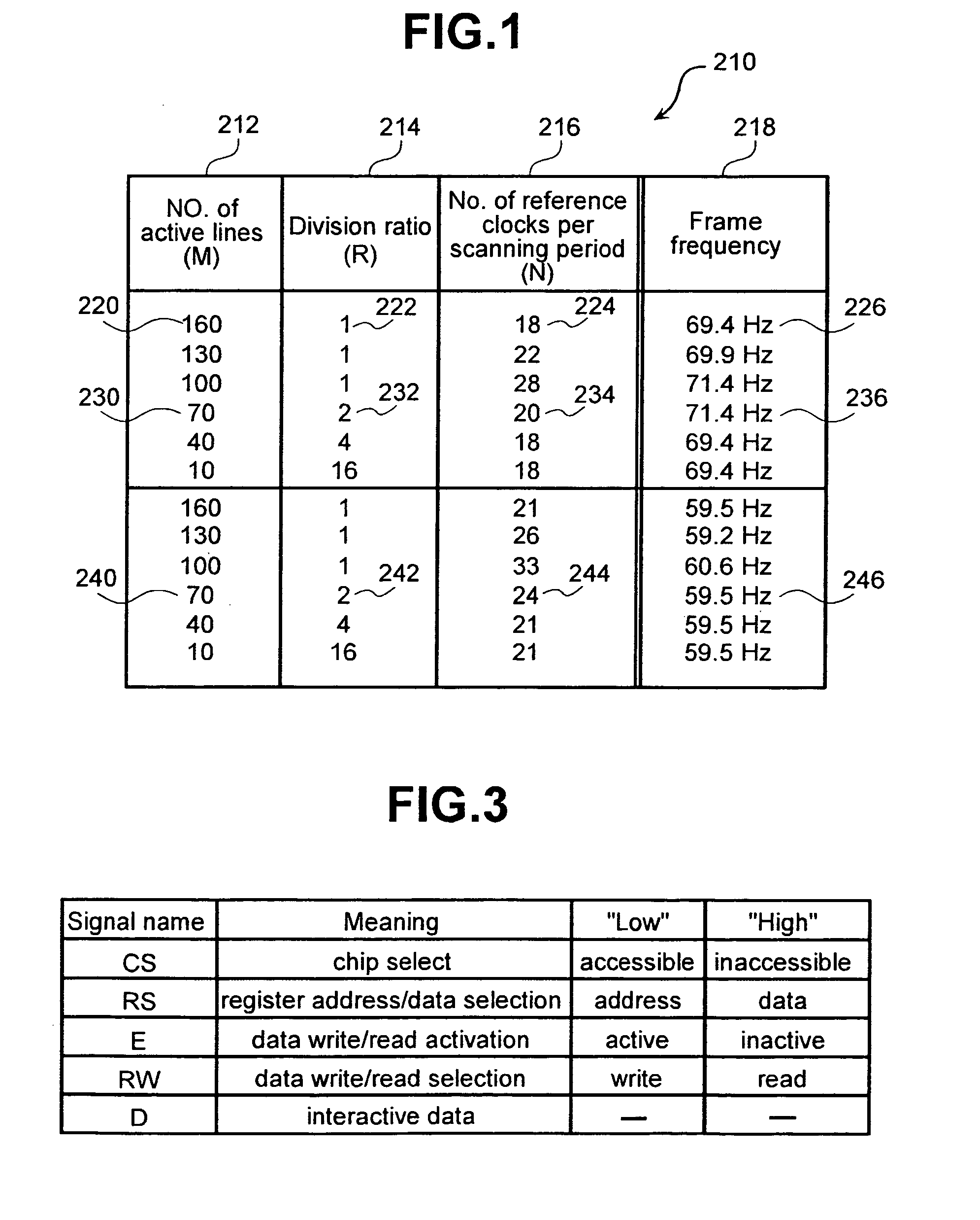
[0065]Now, how the PWM method is applied to the liquid crystal display controller according to the second embodiment of the present invention in order to get 16 gradation steps is discussed next. Div...

first embodiment

[0074]It is assumed here that the waveforms for the data and scanning signals are in accordance with liquid crystal operating voltage waveforms stated on pp. 394–399 of the Liquid Crystal Device Handbook, edited by the 142nd Committee of the Japan Society for the Promotion of Science and published by Nikkan Kogyosha, as in the case of the present invention.

[0075]With the above-mentioned structure and operational sequence, the liquid crystal display controller according to the second embodiment of the present invention can hold the frame frequency virtually constant with different numbers of active lines. In addition, a PWM-based multi-color display can be made.

[0076]Next, further details of the operational sequence of the liquid crystal display controller 902 will be given.

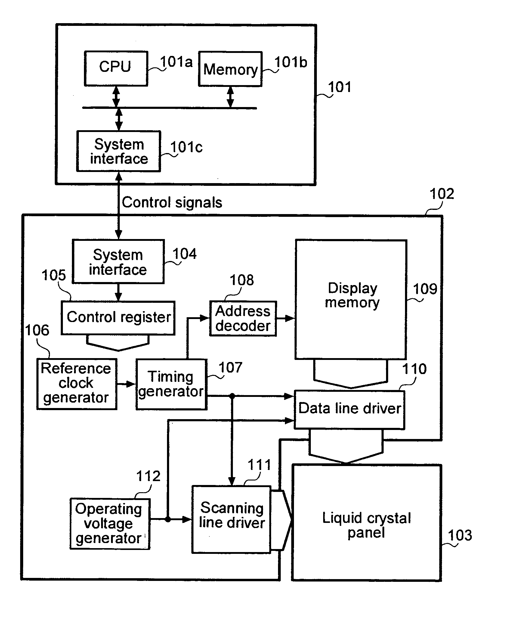
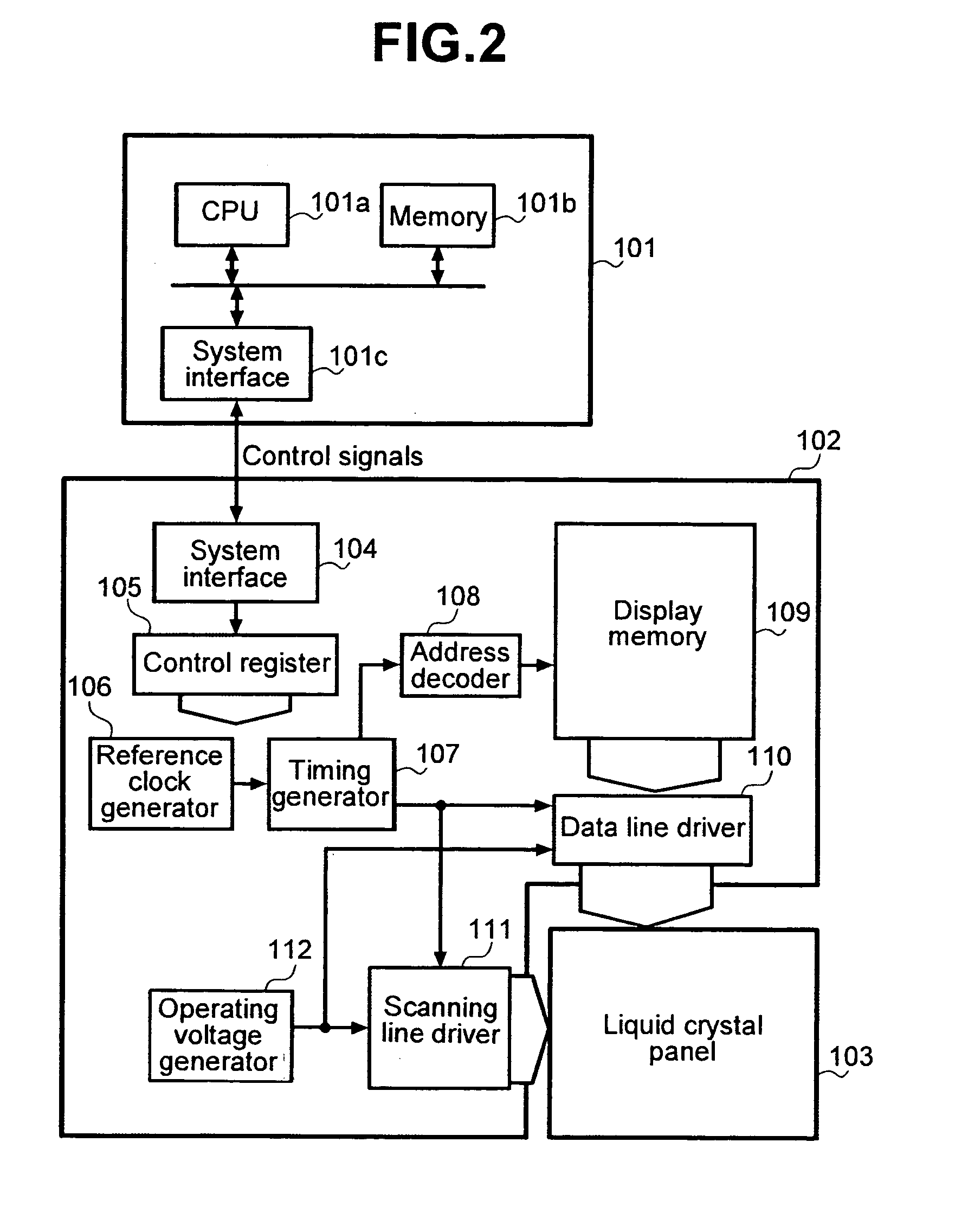
[0077]Descriptions of the system interface 904, control register 905, reference clock generator 906, address decoder 908 and operating voltage generator 912 are omitted here because their structures and operations...

third embodiment

[0085]Next, referring to FIGS. 14 to 18, the present invention will be described.

[0086]In a liquid crystal display controller according to the third embodiment of the present invention, higher image quality and lower power consumption are realized for PWM.

[0087]In every data signal used by the PWM method shown in FIG. 8, except ones for black and white, there are two points of change in voltage level within one scanning period. This is because one scanning period begins with ON voltage and ends with OFF voltage. Therefore, it is not unreasonable to think that by inverting this order every scanning period, the number of data signal changes can be halved. This will halve the power consumed for charge / discharge of the liquid crystal, thereby reducing power consumption. To achieve this, for instance, after the reference clock count 1420 is incremented from 11422 in a scanning period 1410, it should be decremented from 151432 in the next scanning period, as shown in FIG. 14.

[0088]If ther...


PUM

PropertyMeasurementUnit
frequencyaaaaaaaaaa
frequencyaaaaaaaaaa
clock frequencyaaaaaaaaaa

Abstract

The present invention provides a liquid crystal display controller device and method which provides for a full and / or partial display with good display quality and / or low power consumption based on the scanning period for an active scan line being dependent upon a number of reference clock pulses. Some embodiments of the present invention include one or more of the following features: keeping the frequency substantially constant for different numbers of active scan lines, allowing change of the frequency due to characteristics of the LCD, displaying gradation with near linear effective voltage characteristics, displaying graduation data with lower power, or displaying a partial or full screen in a mobile device, for example, a cell phone.

Description

CROSS-REFERENCES TO RELATED APPLICATIONS[0001]This application is related to and claims priority from Japanese Application No. 2000-309300, filed on Oct. 4, 2000 and Japanese Application No. 2000-231351, filed on Jul. 26, 2000.BACKGROUND OF THE INVENTION[0002]The present invention relates to a liquid crystal display (LCD) controller.[0003]An example of a liquid crystal display controller is disclosed by JP-A-No. 11-311980. The controller can drive part of the liquid crystal display selectively as well as can set the operating voltage, operation bias, and reference clock frequency according to the number of active lines in the selected part. This means that when the entire screen need not be displayed, only the required part of the screen can be displayed under proper operating conditions. This leads to reduction in electric power consumption.[0004]In the prior art, the frame frequency is held constant by varying the ratio of division of the original clock depending on the number of ...

Claims


Application Information

Patent Timeline
Patent Type & Authority Patents(United States)
IPC IPC(8): G09G3/36G09G5/02G09G5/00G02F1/133G09G3/20H04N5/66
CPCG09G3/3696G09G3/3611G09G3/2014G09G3/2022G09G2330/021G09G3/36
Inventor KUDO, YASUYUKIFURUHASHI, TSUTOMUYOKOTA, YOSHIKAZUMATSUDO, TOSHIMITSUHIGA, ATSUHIRO
Owner SYNAPTICS JAPAN GK
Why Eureka
Try Eureka