Recordable optical disc, optical disc recording apparatus, optical disc reproduction apparatus, and method for recording data onto recordable optical disc

a technology of optical disc and recording apparatus, which is applied in the field of recording optical disc and optical disc recording and reproducing apparatus, can solve the problems of insufficient accuracy in positioning the edge of the mark, large heat generation of the recording mark, and distortion of the recording mark, and achieve high-speed and high-quality data recording

Inactive Publication Date: 2006-06-27
PANASONIC CORP
View PDF7 Cites 56 Cited by
  • Summary
  • Abstract
  • Description
  • Claims
  • Application Information

AI Technical Summary

Benefits of technology

[0071]An object of the invention is to provide a recordable optical disk, an optical disk recording and reproducing apparatus, and its method of recording and reproducing, which optimize the write strategy and the recording power level for any recording speeds from single- to n-times speeds within a short time, thereby achieving high-speed and high-quality data recordings.

Problems solved by technology

The formation of the recording marks generates large amounts of heat at the portions of the recording layer radiated with the laser light.
Such variables cause distortions of the recording marks.
Accordingly, the formation of the recording marks, especially the positioning of the mark edges is performed with an insufficient accuracy when the recording pulses and the recording power levels are determined merely according to standards of write strategy and recording power condition.
This causes high error rates of data actually recorded.
The distortions cause errors in the data recording.
As a result, power levels of the laser light are low in the front ends of the pulses, and thereby cause front edges of the recording marks to taper.
This increases error rates of data.
In particular, the multi-pulses with short pulse intervals cause excessive amounts of heat to be built up in the recording layer.
In addition, the above-mentioned excessive amount of heat, when propagating through the recording space to the subsequent recording mark, distorts the front edge of the recording mark, thereby causing the edge shifts of the digital signal to be increased at the front mark edges.
The above-described increases of the edge shifts increase error rates of data.
However, even ordinary level of the recording power causes excessive amounts of heat to be built up in the latter half portion of the recording mark M2.
Accordingly, the increase in recording power level largely distorts the recording marks, thereby increasing the edge shifts and error rates of data, contrary to expectations.
Thus, the prior art optical disk recording and reproducing apparatus substantially reduces the recording power margins with the increases in recording speed, thereby reducing its reliability of the data recordings.
This reduces the SIN ratios of the wobble signal and the LPP signal, thereby increasing errors of reading addresses.
However, the changes of the write strategies and the recording power conditions depending on the recording speeds cause the following problem.
Furthermore, no information on the recording speed corresponding to the above-mentioned write strategy and recording power condition is store on the prior art optical disks.
Thereby, reductions of error rates of data are difficult through the above-described correction of write strategy and OPC.
In this case, the recording power level is insufficient for the top pulses, but excessive for the multi-pulses.
Since the difference between the insufficiency and the excess is generally large, the optimization is difficult by means of the above-described correction of write strategy.
Therefore, the adjusting time excessively increases the time for the correction of write strategy, thereby delaying the start of the data recording onto the optical disk.

Method used


Image

  • Recordable optical disc, optical disc recording apparatus, optical disc reproduction apparatus, and method for recording data onto recordable optical disc
  • Recordable optical disc, optical disc recording apparatus, optical disc reproduction apparatus, and method for recording data onto recordable optical disc
  • Recordable optical disc, optical disc recording apparatus, optical disc reproduction apparatus, and method for recording data onto recordable optical disc

Examples


example 1

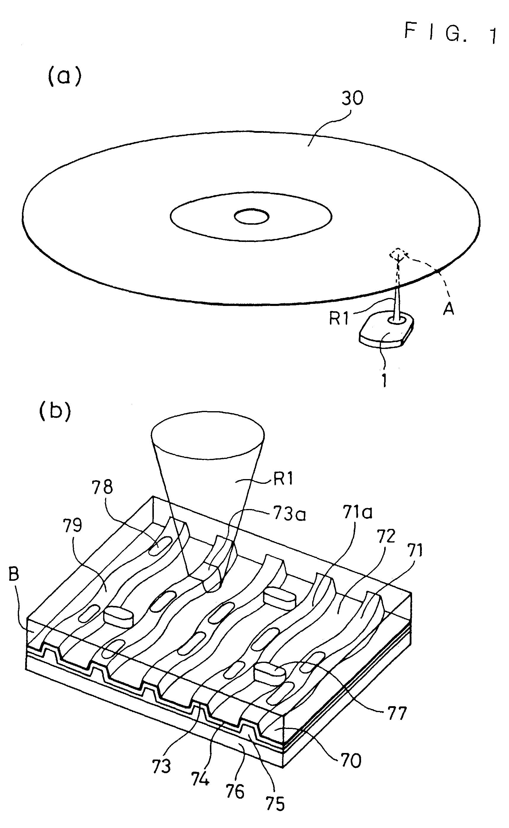
[0253]The following describes a DVD-R 30 serving as a recordable optical disk according to Example 1 of the invention. The part (a) of FIG. 1 is a perspective view showing the overall appearance of the DVD-R 30 and the appearance of a radiation by a pickup 1 of a DVD-R recorder with laser light R1. The part (b) of FIG. 1 is an enlarged view of a small area A surrounded by broken lines in (a) of FIG. 1 when viewed from the back side. A cross section B of the DVD-R 30 perpendicular to its surface and parallel to its radial direction is shown in (b) of FIG. 1.

[0254]The DVD-R 30 is a disk based on the standard, the DVD-R for General Ver. 2.0, and measuring about 120 mm in diameter and about 1.2 mm in thickness. The disk substrate 70 measures about 0.6 mm in thickness and is made of polycarbonate. The surface of the disk substrate 70 comprises grooves 71. The grooves 71 are a spiral groove concentric with the disk substrate 70. The groove 71 has a wobble 71a, i.e., a transversely and fin...

example 2

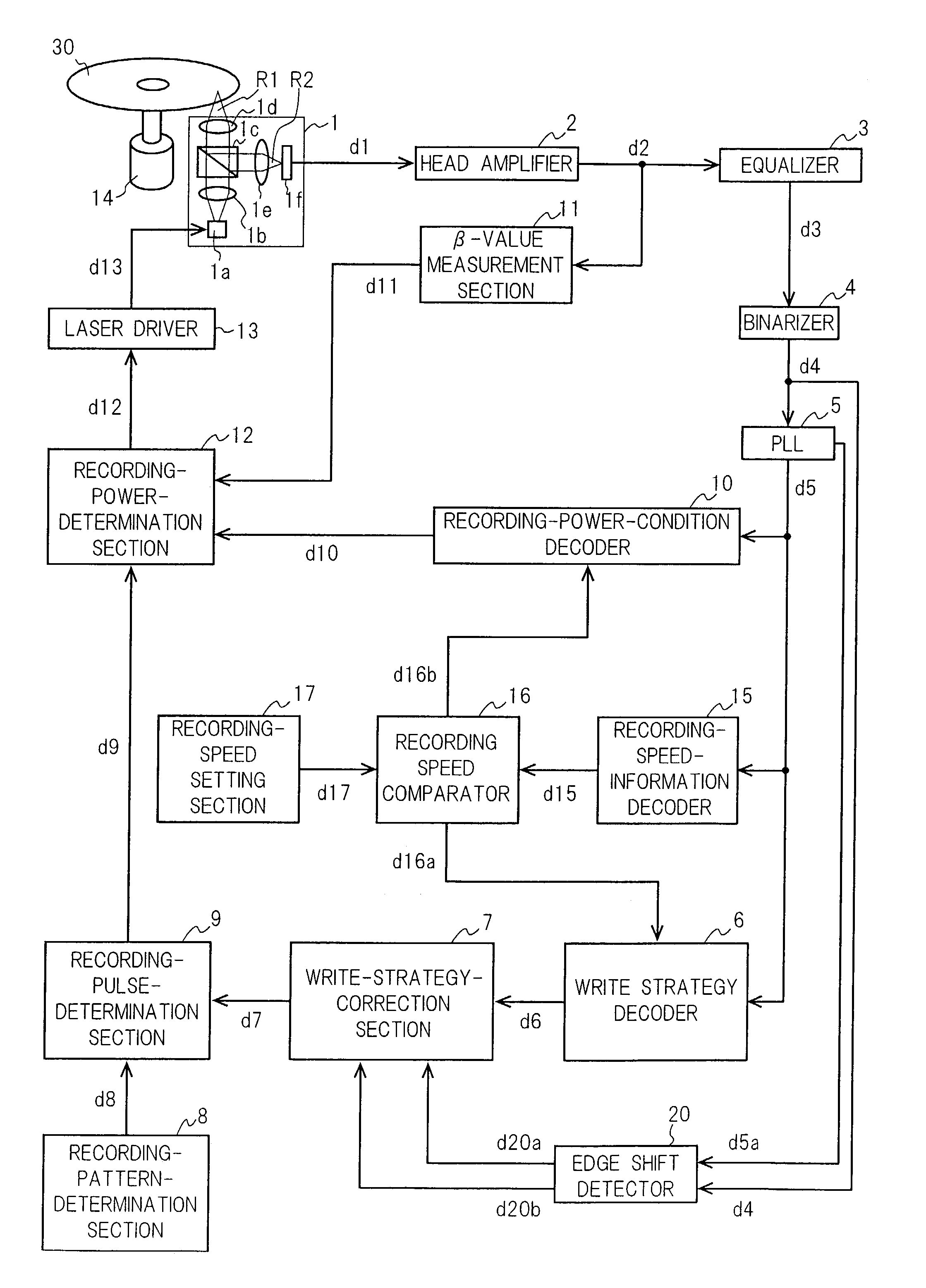
[0293]FIG. 4 is a block diagram showing a DVD-R recorder according to Example 2 of the invention.

[0294]A DVD-R 30 is a DVD-R similar to the above-described one of Example 1 of the invention. A spindle motor 14 revolves the DVD-R 30 around its center axis. Then, the revolution per minute of the spindle motor 14 is controlled such that the line velocity of the DVD-R 30 is maintained substantially constant at the focus of the laser light R1 from a pickup 1. The line velocity is set, to be equal to a positive integral multiple of the standard speed 3.49 m / s.

[0295]The pickup 1, at the time of data reproduction, radiates the DVD-R 30 with laser light R1 and converts the reflected light R2 into an analog signal d1 as follows. A semiconductor laser 1a emits the laser light R1 at a predetermined power level. The power level (reproducing power) is too low to change the property of the recording layer of the DVD-R 30, that is, approximately 0.7–1 mW. The laser light R1 emitted by the semicondu...

example 3

[0372]FIG. 9 is a block diagram showing a DVD-R recorder according to Example 3 of the invention. In contrast to the DVD-R recorder according to Example 2 (See FIG. 4), the DVD-R recorder according to Example 3 comprises a block error rate detector 20A in place of the edge shift detector. In FIG. 9, the same reference symbols as those in FIG. 4 designate components similar to those of Example 2 shown in FIG. 4. Furthermore, the description of Example 2 is cited as details of the similar components.

[0373]The block error rate detector 20A compares the digital signal d5 from the PLL 5 with the test recording pattern d8 from the recording-pattern-determination section 8 and detects the block error rate of the digital signal d5. Here, the block error rate refers to the error rate of the digital signal d5 measured for each of the ECC blocks of the DVD-R 30. Each of the ECC blocks comprises 16 sectors and each of the sector is available for recorded data of substantially 182 bytes×13 in am...


PUM

PropertyMeasurementUnit
thicknessaaaaaaaaaa
diameteraaaaaaaaaa
thicknessaaaaaaaaaa

Abstract

A DVD-R recorder according to the invention detects an item of recording speed information (d15) from a DVD-R (30) on which histories of recording speed information, write strategy, and recording power condition are stored. When the decoded item of recording speed information (d15) agrees with a set item of recording speed information (d17), the recorder detects the write strategy (d6) and the recording power condition (d10) corresponding to the decoded item of recording speed information (d15). A recording-pulse-determination section (9) converts a recording pattern (d8) into a recording pulse (d9) according to the write strategy (d6). A recording-power-determination section (12) performs an OPC based on the recording power condition (d10). The recording power condition (d10) may include information specifying that a recording pulse corresponding to the front edge of a recorded mark has a larger recording power than other recording pulses.

Description

CROSS-REFERENCE TO RELATED APPLICATION[0001]This application is a Section 371 of PCT / JP02 / 04007, filed Apr. 22, 2002, the disclosure of which is incorporated herein by reference.TECHNICAL FIELD[0002]The present invention relates to recordable optical disks and optical disk recording and reproducing apparatuses and, in particular, a method for determining a write strategy and a recording power level.BACKGROUND ART[0003]Optical information recording technology, i.e., the technology for recording data onto recordable optical disks has remarkably advanced in recent years. With the advance of the technology, various types of optical disk recording and reproducing apparatuses have been developed. In particular, the applications to storage devices external to computers, such as DVD-RAM drives, have come into widespread use.[0004]Here, optical information recording technology especially refers to the following recording technology. An optical head (which is also referred to as a pickup) rad...

Claims


Application Information

Patent Timeline
Patent Type & Authority Patents(United States)
IPC IPC(8): G11B7/00G11B7/004G11B7/0045G11B7/007G11B7/125G11B7/24
CPCG11B7/00456G11B7/1267G11B7/00736G11B7/0045
Inventor TASAKA, SHUICHISHOJI, MAMORU
Owner PANASONIC CORP
Why Eureka
Try Eureka