Multi-clad doped optical fiber

a fiber laser/amplifier, multi-clad technology, applied in the field of optical fibers, can solve the problems of limiting and the output power of the output power of the fiber laser/amplifier

Inactive Publication Date: 2006-06-27
INSTITUT NATIONAL D'OPTIQUE
View PDF16 Cites 45 Cited by
  • Summary
  • Abstract
  • Description
  • Claims
  • Application Information

AI Technical Summary

Benefits of technology

[0011]Therefore, in accordance with the present invention, there is provided a triple-clad fiber comprising an intermediate cladding inserted between an inner core and an outer core of the triple-clad fiber, in order to increase the range of possible characteristics of the core, such as, for example, enlarging the cross-section of the fiber core or increasing the dopant density in the core. More generally, the invention provides a multi-clad fiber, with three claddings or more, where at least one intermediate cladding is inserted between an inner core and an outer core of the multi-clad fiber, for enlarging the cross-section of the fiber core or for increasing the dopant density in the core. The invention also provides an intermediate cladding having a multi-layer structure to better confine the pump power in a suitable pumping region of the fiber. The multi-clad fibers may comprise any kind of optical fiber cores: single-mode, slightly multi-mode or multi-mode.

Problems solved by technology

Limiting the pump diode active area limits its output power proportionally, which in turn limits the output power of the fiber laser / amplifier.
The challenge remains to optimize the efficiency of the amplifier fiber.

Method used


Image

  • Multi-clad doped optical fiber
  • Multi-clad doped optical fiber
  • Multi-clad doped optical fiber

Examples


Embodiment Construction

[0034]In the following description of the embodiments, reference to the accompanying drawings are by way of illustration of an example by which the invention may be practiced. It will be understood that other embodiments may be made without departing from the scope of the invention disclosed.

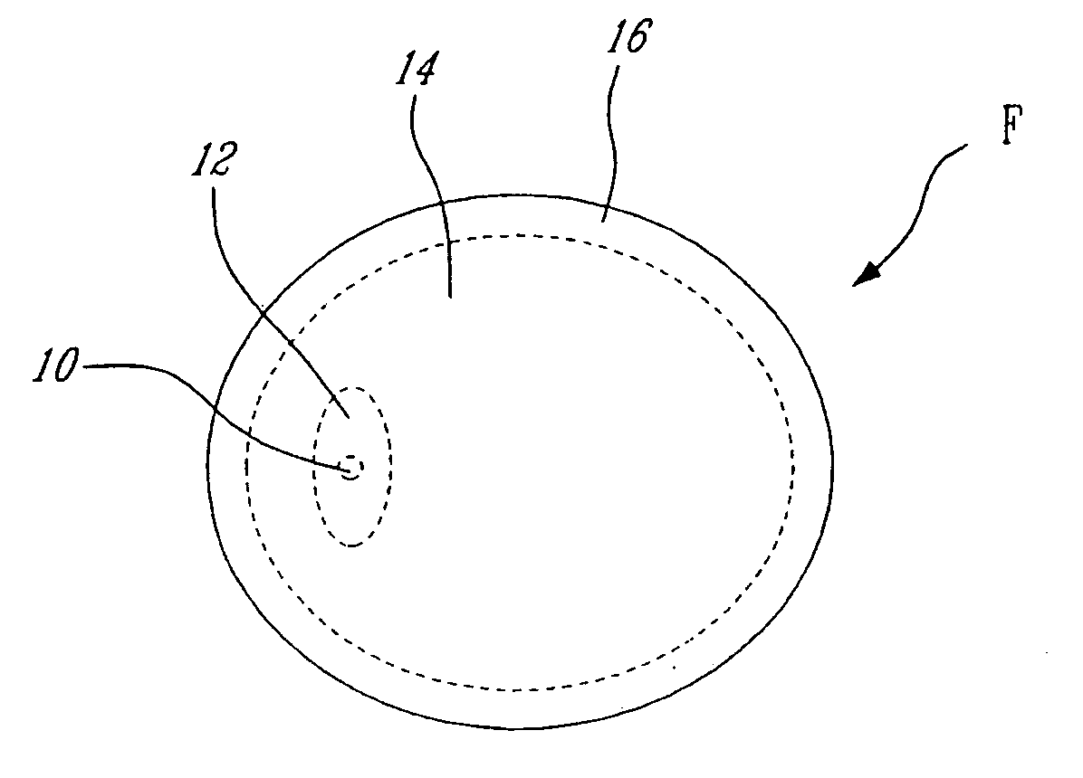
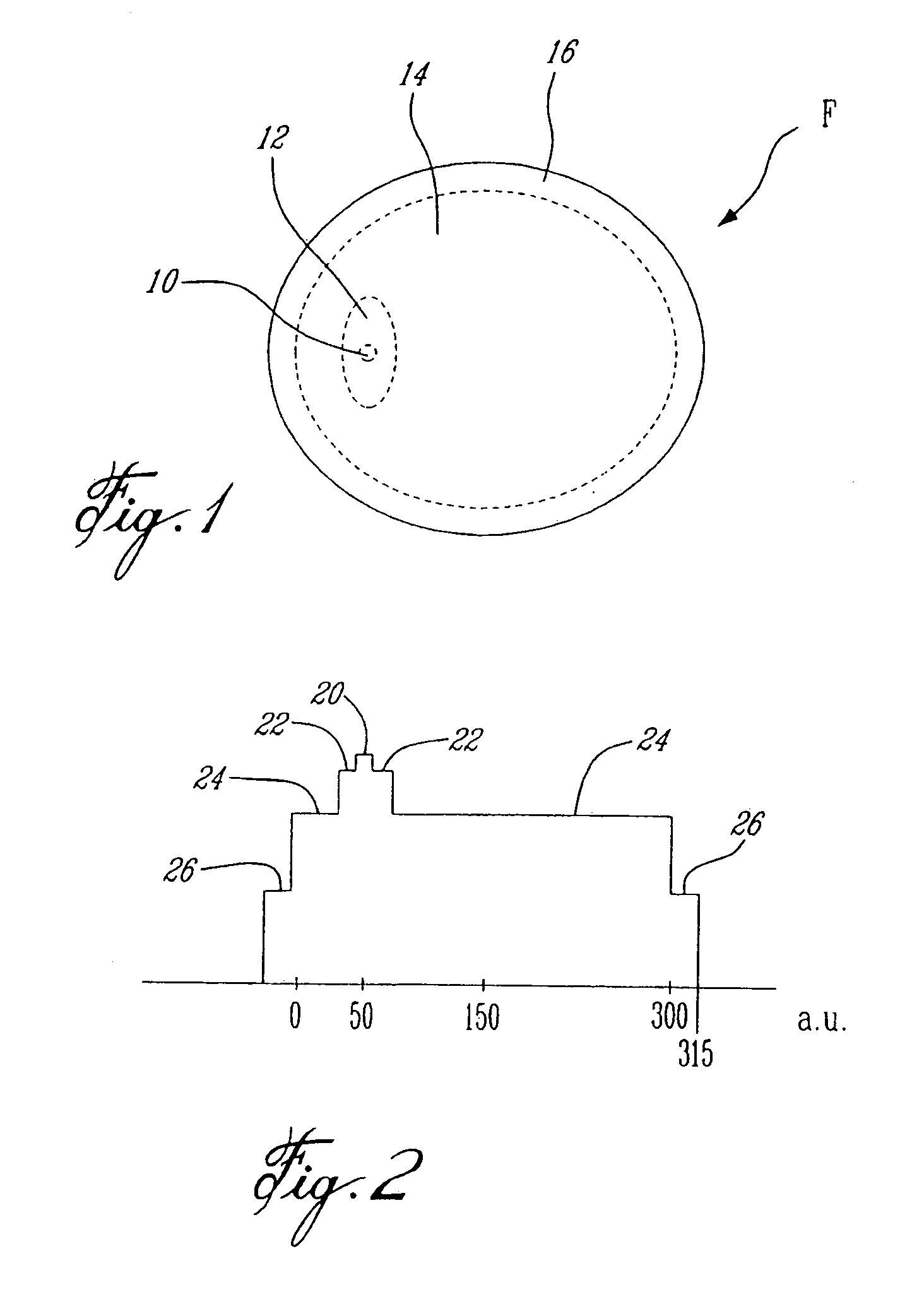
[0035]A first embodiment of the present invention consists in a rare-earth doped optical fiber F which has a triple-clad geometry. More particularly, the optical fiber F comprises an inner core 10 and, inward out, a first inner cladding 12, a second intermediate cladding 14 and a third outer cladding 16. The core 10 represents the waveguide section of higher refractive index through which the signal is transmitted and amplified. In this embodiment, the core 10 is a singlemode core and is doped with rare-earth elements useful for the transfer of energy between the pump and signal. In alternative embodiments, the core 10 can be slightly multi-mode or multi-mode. The first cladding 12 of the core 1...


PUM


Abstract

The invention provides a multi-clad fiber, with three claddings or more, where at least one intermediate cladding is inserted between an inner core and an outer core of the multi-clad fiber, for enlarging the cross-section of the fiber core or for increasing the dopant density in the core. The invention also provides an intermediate cladding having a multi-layer structure to better confine the pump power in a suitable pumping region of the fiber.

Description

RELATED APPLICATIONS[0001]This application is a continuation-in-part of pending U.S. patent application Ser. No. 10 / 241,239 filed Sep. 11, 2002, which is a continuation of U.S. patent application Ser. No. 09 / 593,272 filed Jun. 13, 2000, now abandoned, all of which are hereby incorporated by reference.FIELD OF THE INVENTION[0002]The present invention relates to the field of optical fibers and, more particularly, to high output power fiber amplifiers or lasers.BACKGROUND OF THE ART[0003]There is a demand to increase the output power of fiber amplifiers / lasers. This demand is motivated by DWDM (Dense Wavelength Division Multiplexing) optical communication where multiple data channels have to be amplified simultaneously sharing the available amplifier output power with one another. Another growing application is OISL (Optical Inter-Satellite Links), where a diffraction-limited beam has to be emitted in free-space and received thousands of kilometers away. In this last case, the propagat...

Claims


Application Information

Patent Timeline
Patent Type & Authority Patents(United States)
IPC IPC(8): G02B6/02G02B6/00G02B6/036
CPCG02B6/03605G02B6/03661G02B6/03638
Inventor CROTEAU, ANDRETAILLON, YVESLAUZON, JOCELYN
Owner INSTITUT NATIONAL D'OPTIQUE
Why Eureka
Try Eureka