Tunable ferroelectric resonator arrangement

a resonator and ferroelectric technology, applied in the direction of resonators, superconductors/hyperconductors, electrical devices, etc., can solve the problems of reducing the quality factor (q-value) of the ferroelectric substrate or element, and finding no satisfactory solution to the problem of induced losses in tunable ferroelectric resonators, etc., to reduce the effect of induced increasing losses

Inactive Publication Date: 2006-06-27
TELEFON AB LM ERICSSON (PUBL)
View PDF21 Cites 230 Cited by
  • Summary
  • Abstract
  • Description
  • Claims
  • Application Information

AI Technical Summary

Benefits of technology

[0009]An arrangement is also needed which is compact in size for use in different types of components, which can be tuned efficiently without requiring too high amounts of power, and which is reliable in operation. Moreover an arrangement is needed which is robust and which has a satisfactory tuning selectivity and tuning sensitivity, and through which the insertion losses are low or can be compensated for.
[0016]Through the application of a tuning (biasing) voltage to said second resonator, electromagnetic energy will be distributed to the first resonator and, particularly, as the biasing voltage increases, more and more electromagnetic energy will be distributed or transferred to the first resonator since the resonators are coupled the way they are. This means that the distribution of electromagnetic energy between the first and second resonators depends on the biasing (tuning) voltage or the electric field and of course the coupling means. The resonating frequency in the second resonator increases with the application of an increasing biasing voltage. As the biasing voltage increases, also the loss tangent of the second, ferroelectric, resonator will increase, at the same time as less of the electromagnetic energy will be located in it. Thereby will automatically be compensated for the increased loss tangent of the second resonator in that the influence thereof on the coupled resonator apparatus comprising the first and the second resonators will be reduced.
[0019]According to the invention, for coupling a first and a second resonator to each other, the coupling means may comprise, for each resonator apparatus, a slot or an aperture in the common ground plane. The resonators may be of substantially any appropriate shape, they may e.g. be circular, square-shaped, rectangular or ellipsoidal etc. The shape of the first resonator may also differ from that of the second resonator. The resonator apparatus may also be a dual mode resonator apparatus. Then each resonator comprises mode coupling means such as for example a protrusion, a cut-out or any other means to provide for dual mode operation. Examples thereon are provided in the patent applications incorporated herein by reference. According to the invention it can be said that tunability and losses is exchanged or distributed between the two resonators of a resonator apparatus, thereby reducing the effect of the induced increasing losses caused by the electrical tuning.

Problems solved by technology

However, this device as well as other resonators and filters based on ferroelectric materials suffer from the drawback of the quality factor (Q-value) of the ferroelectric substrate or element decreasing drastically with the applied voltage, when a biasing voltage is applied.
However, so far, no satisfactory solution to the problem associated with induced losses in tunable ferroelectric resonators has been found.

Method used


Image

  • Tunable ferroelectric resonator arrangement
  • Tunable ferroelectric resonator arrangement
  • Tunable ferroelectric resonator arrangement

Examples


Embodiment Construction

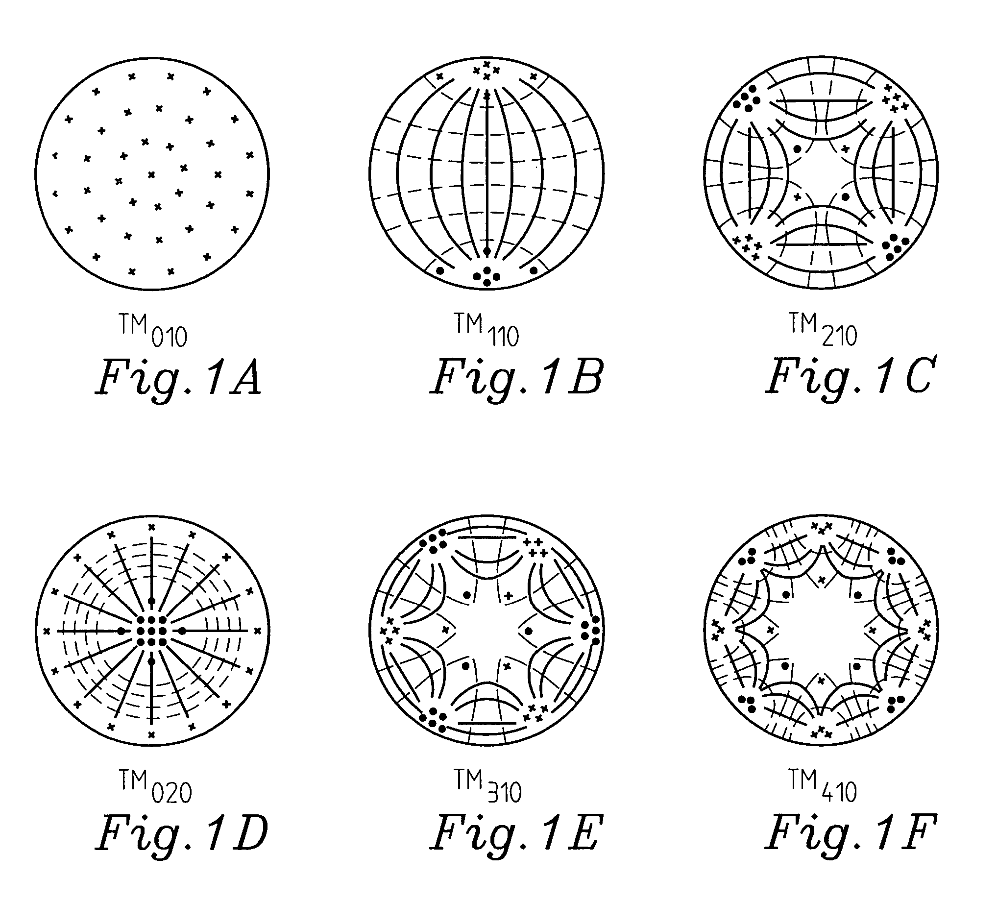
[0039]FIGS. 1A–1F disclose, for illustrative purposes, the lower order TMnmp field distributions for a circular parallell plate resonator, i.e. the TM010, TM110, TM210, TM020, TM310, TM410-modes. Solid lines indicate the current, dashed lines indicate the magnetic field and dots and crosses indicate the electric field. It is supposed that p=0, i.e. that the thickness of the substrate is smaller than half a wavelength in the resonator, and that the resonator only supports TMnm0-modes. The field / current distributions are fixed in space by coupling arrangements (such as coupling loops, coupling probes, or a further resonator).

[0040]Parallel plate resonators, for example in the form of circular dielectric disks and circular patches on dielectric substrates, have found several different microwave applications. The resonators are seen as electrically thin if the thickness (d) is smaller than half the wavelength of the microwave (λg) in the resonator, dg / 2, so that no standing waves will b...


PUM

PropertyMeasurementUnit
dielectric constantaaaaaaaaaa

Abstract

The present invention relates to a tunable resonating arrangement comprising a resonator apparatus (10), input / output coupling (4) means for coupling electromagnetic energy into / out of the resonator apparatus, and a tuning device (3) for application of a biasing voltage / electric field to the resonator apparatus. The resonator apparatus comprises a first resonator (1) and a second resonator (2). Said first resonator is non-tunable and said second resonator is tunable and comprises a ferroelectric substrate (21). Said first and second resonators are separated by a ground plane (13) which is common for said first and second resonators, and coupling means (5) are provided for providing coupling between said first and second resonators. For tuning of the resonator apparatus, the biasing voltage / electric field is applied to the second resonator (2).

Description

[0001]This application is a continuation of PCT International Application No. PCT / SE02 / 01461, filed in English on 16 Aug. 2002, which designated the US. PCT / SE02 / 01461 claims priority to SE Application No. 0102785-3 filed 22 Aug. 2001. The entire contents of these applications are incorporated herein by reference.FIELD OF THE INVENTION[0002]The present invention relates to a tunable resonating arrangement which comprises a resonator apparatus. Electromagnetic energy is coupled into / out of the resonator apparatus over input / output coupling means, and for tuning of the resonator apparatus, a tuning device is used for application of a biasing / tuning voltage (electric field) to the resonator apparatus. The invention also relates to such a resonator apparatus, a tunable filter arrangement, and to a method of tuning a resonating arrangement.STATE OF THE ART[0003]Electrically tunable resonators are attractive components for agile radar and mobile radio communication systems. Different type...

Claims


Application Information

Patent Timeline
Patent Type & Authority Patents(United States)
IPC IPC(8): H01P7/08H01B12/02H01P1/203H01P1/20H01P7/10
CPCH01P7/10H01P1/20H01P1/203
Inventor GEVORGIAN, SPARTAKDELENIV, ANATOLYVENDIK, ORESTKOLLBERG, ERIKWIKBORG, ERLAND
Owner TELEFON AB LM ERICSSON (PUBL)
Why Eureka
Try Eureka