Magnetic field gradient coil assembly and method of designing same

a gradient coil and magnetic field technology, applied in the direction of superconducting magnets/coils, instruments, magnetic bodies, etc., can solve the problems of large approximation error, difficult to wind the wire completely in accordance, and more difficult to accurately fabricate the coils. , to achieve the effect of simple structure, large inside diameter and high approximation accuracy

Inactive Publication Date: 2006-06-27
JEOL RESONANCE
View PDF10 Cites 8 Cited by
  • Summary
  • Abstract
  • Description
  • Claims
  • Application Information

AI Technical Summary

Benefits of technology

[0020]It is an object of the present invention to provide a magnetic field gradient coil assembly that provides high approximation accuracy, is simple in structure, has a large inside diameter, permits small-sized self-shielding coils to be designed, and responds at a sufficient speed to be used in high-resolution NMR spectrometers. It is another object of the present invention to provide a method of designing this magnetic field gradient coil assembly.

Problems solved by technology

However, as the coils decrease in size, it becomes more difficult to fabricate the coils accurately, that is, it is necessary to wind conductive wire into a bobbin shape (i.e., distributed winding) according to the calculated coil geometry in order to obtain the current distributions found by calculations.
Hence, it is difficult to wind the wire completely in accordance with the coil geometry.
If the number of turns of wire is few, the approximation error becomes large.
This deteriorates the performance.
This is not a realistic solution.
However, this cannot be achieved for the following reason.
However, this approach is difficult to accomplish because of coil resistance and restrictions on the mechanical dimensions.
Furthermore, electric interference between a DC magnetic field gradient coil and the detection coil operating at hundreds of megaherz is large, lowering the Q of the detection coil.
However, this shield heavily interferes with the detection coil.

Method used


Image

  • Magnetic field gradient coil assembly and method of designing same
  • Magnetic field gradient coil assembly and method of designing same
  • Magnetic field gradient coil assembly and method of designing same

Examples


Embodiment Construction

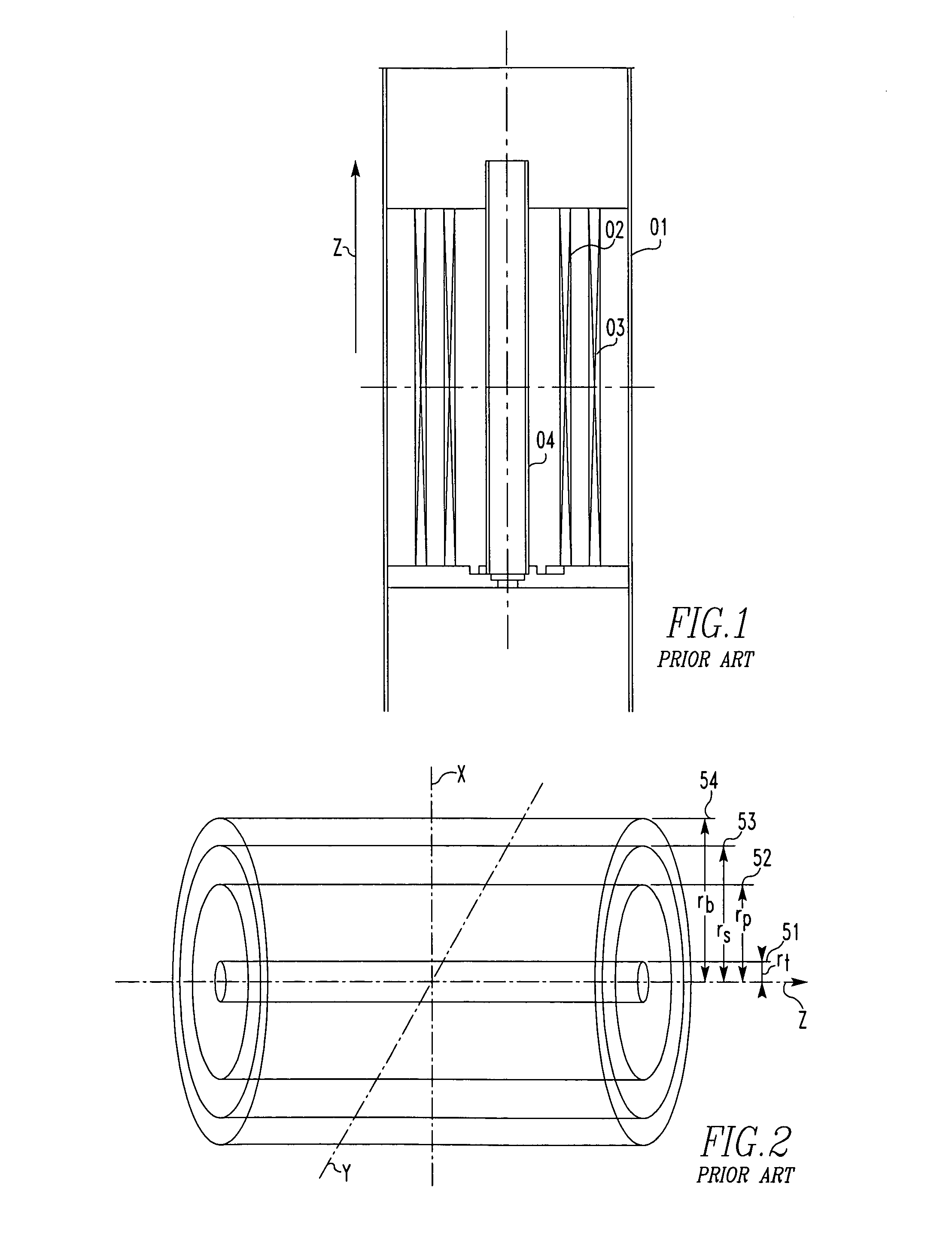
[0043]The preferred embodiments of the invention are hereinafter described. In the following description, the NMR detector of the structure described in connection with FIG. 1 and the system of coordinates and the coil bobbin used for designing and calculations already described in conjunction with FIG. 2 are also used. Accordingly, in the same way as in the prior art structure described previously, the detector of interest has a coil bobbin formed by cylinders 51, 52, 53, and 54, which are also referred to as cylinder 1, cylinder 2, cylinder 3, and cylinder 4, respectively. These cylinders 51, 52, 53, and 54 have radii of rt, rp, rs, and rb, respectively. The radius rt of cylinder 1 is the radius of a target magnetic field taking the form of the cylinder 51. The radius rp is the radius of the primary, inner coil, or the cylinder 52. The radius rs is the radius of the outer screen coil, or the cylinder 53. The radius rb is the radius of the boundary defined by the cylinder 54. An ex...


PUM

PropertyMeasurementUnit
magnetic fieldaaaaaaaaaa
magnetic field strengthaaaaaaaaaa
electric current spatial distributionaaaaaaaaaa

Abstract

A method of designing a small-sized, self-shielding magnetic field gradient coil assembly that is for use in an NMR spectrometer, provides high approximation accuracy, is simple in structure, and has a large inside diameter. The gradient coil assembly consists of tightly wound inner and outer coils. The designing process starts with setting or resetting the number of the inner coils and the number of turns of each inner coil. Their positions are optimized such that the magnetic field gradient strength falls within a tolerable range under shielded condition. Then, the number of the outer coils and the number of turns of each outer coil are set. The Fourier components of a current distribution necessary for the outer coils are calculated.

Description

BACKGROUND OF THE INVENTION[0001]1. Field of the Invention[0002]The present invention relates to a method of designing a magnetic field gradient coil assembly used in a nuclear magnetic resonance (NMR) spectrometer or the like and to a magnetic field gradient coil assembly designed by such a method.[0003]2. Description of the Related Art[0004]NMR spectrometers have adopted self-shielding magnetic field gradient coils because quickly rising magnetic field gradient pulses are applied to specimens. The designing procedures used heretofore are now summarized by referring to FIGS. 1–4. The designing procedures use the target field method as described by R. Tuner in A Target Field Approach to Optimal Coil Design, J. Phys. D: Appl. Phys. 19, L147–L151 (1986) and by P. Mansfield and B. Chapman in Multishield Active Magnetic Screening of Coil Structures in NMR, J. Magn. Reso. 72, pp. 211–223 (1987). In the target field method, the distributions of electric currents flowing through virtual in...

Claims


Application Information

Patent Timeline
Patent Type & Authority Patents(United States)
IPC IPC(8): G06F7/60G01R33/20G01V3/00A61B5/055G01R33/385G01R33/421G06F17/14H01F6/06H01F7/20
CPCG01R33/4215G01R33/385
Inventor HASEGAWA, KENICHI
Owner JEOL RESONANCE
Why Eureka
Try Eureka