Eureka AIR delivers breakthrough ideas for toughest innovation challenges, trusted by R&D personnel around the world.

Magneto-rheological damper

a damper and magneto-rheological technology, applied in the field of magneto-rheological dampers, can solve the problems of inability to accurately classify, additional damping, and adaptation of magneto-rheological dampers, and achieve the effect of improving response characteristics

Inactive Publication Date: 2006-07-04
BOSCH REXROTH AG
View PDF21 Cites 11 Cited by
  • Summary
  • Abstract
  • Description
  • Claims
  • Application Information

AI Technical Summary

Benefits of technology

[0013]It is an object of the present invention to furnish an MR damper which eliminates the named drawbacks and thus exhibits substantially improved response characteristics.
[0016]The essential advantage of the preferred arrangement of the electrical coils externally of the housing cavity resides in the fact that the electrical coils may be replaced rapidly and easily, so that a corresponding adaptation of the MR damper to the conditions of use may be realized.

Problems solved by technology

Frequently the single principles are mixed, however, so that an accurate classification is not possible.
Moreover the fluid flowing through the openings is sheared across the free cross-section on the stationary housing inner wall and the moving piston, resulting in additional damping.
It is a drawback in this solution that the coil is mounted on the piston, so that an adaptation of the MR damper to the conditions of the respective task (damping properties) by simple and rapid replacement of the coil is not possible.
Optimum adaptation of the MR damper to different damping conditions accordingly is not possible.
It is another drawback of the known solution that damping takes place not so much through the viscosity of the fluid than rather the cross-section of the openings in the piston and the related throttling effect.
In other words, the flow and creep properties of the magneto-rheological fluid are not put to optimum use.
It is another drawback of this solution that when a load is applied, the valve mode may possibly create a considerable pressure differential between the cylinder-swept volume and the cylinder volume, with all the components of the MR damper, in particular seals, having to be designed with corresponding adaptations.
It is a drawback of this solution that the entire housing cavity is exposed to the magnetic field, with damping accordingly being achieved not so much by squeezing the fluid in the piston-swept volume or through the annular space, but rather by pinching of the piston in the fluid.

Method used


Image

  • Magneto-rheological damper
  • Magneto-rheological damper
  • Magneto-rheological damper

Examples


Embodiment Construction

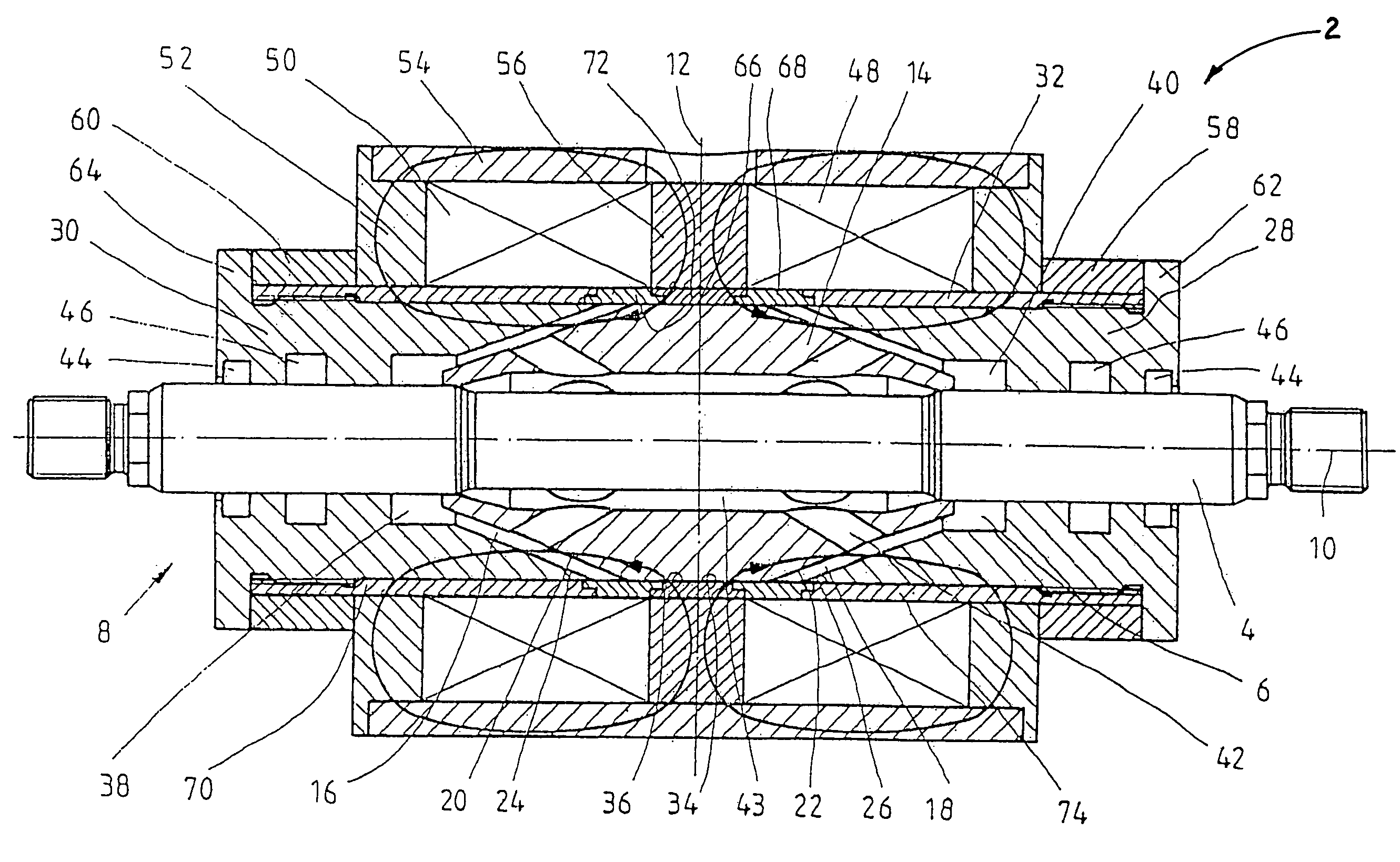
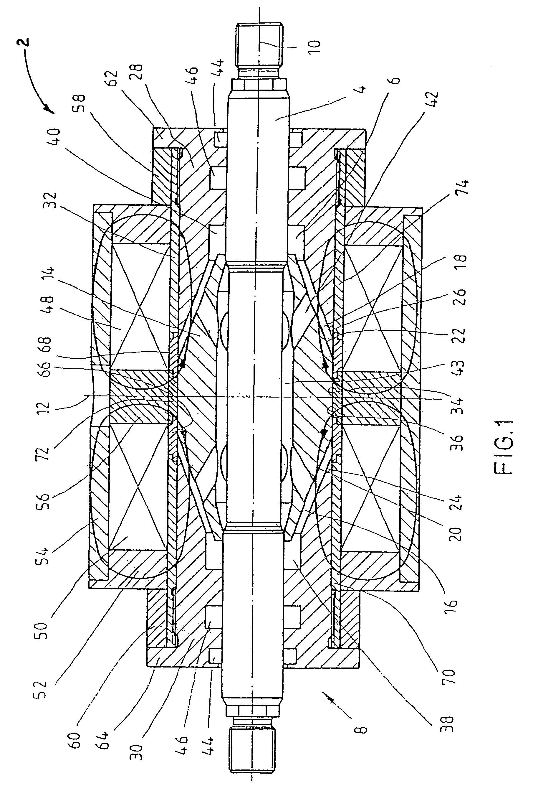
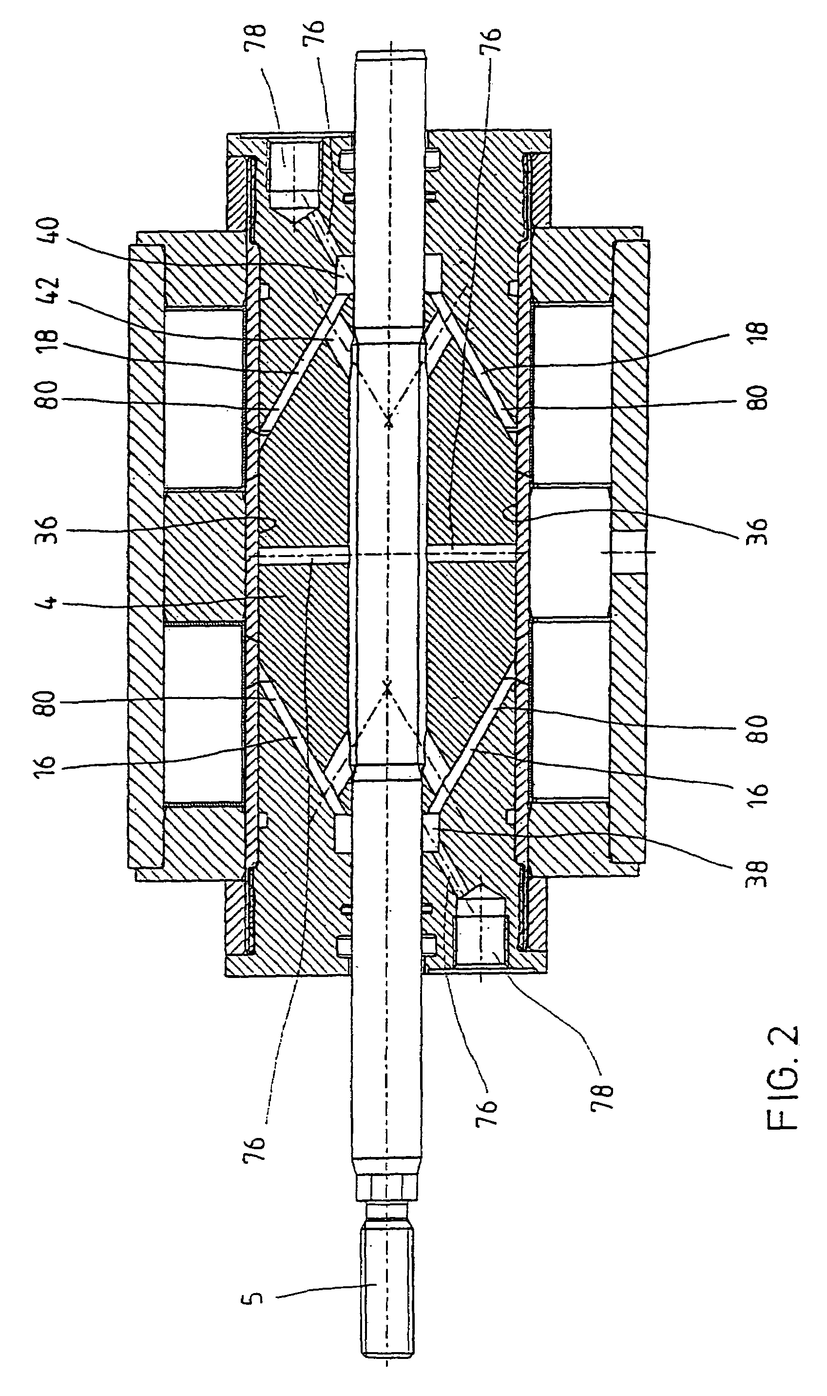
[0026]FIG. 1 shows a magneto-rheological (MR) damper 2 in accordance with the invention which includes a piston 4 on a magnetically non-conductive piston rod 5 (see FIG. 2), which is guided in a damper cavity 6 of a cylinder 8 filled with a magneto-rheological fluid. The MR damper 2 is of a symmetrical design relative to a transverse axis 12 extending transversely to the longitudinal axis 10, whereby a damping stroke in both axial directions of movement is achieved, so that tensile and compressive forces may be damped.

[0027]The piston 4, also referred to as an armature, forms between its inner cone surfaces 20, 22 of the cylinder 8 and its correspondingly shaped outer cone surfaces 24, 26 two annular spaces 16, 18 extending obliquely to the piston axis 10. Owing to the oblique orientation of the annular spaces 16, 18 the annular space volume is increased in contrast with axially oriented annular spaces, so that correspondingly more fluid is available for damping of the piston 4. The...


PUM


Abstract

A magneto-rheological (MR) damper including a piston guided in a cylinder that is filled with a magneto-rheological fluid, its work volume being formed oblique relative to the piston axis between the piston and the cylinder.

Description

BACKGROUND OF THE INVENTION[0001]1. Field of the Invention[0002]The invention concerns a magneto-rheological (MR) damper, and more particularly, an MR damper that is readily adaptable to the conditions of the damping properties.[0003]2. Description of the Related Art[0004]MR dampers include a magneto-rheological fluid, a work volume to which the fluid is applied, and an element for generating a magnetic field, wherein the yield limit of the fluid may be modified by application of the magnetic field.[0005]A housing cavity is divided by a piston into a piston-swept volume and a cylinder volume, with the fluid being capable of flowing between the volumes through openings. In principle, MR dampers operating in the Valve Mode, Shear Mode, or Squeeze Mode are known. Frequently the single principles are mixed, however, so that an accurate classification is not possible.[0006]A MR damper operating, e.g., in the valve and shear modes is disclosed in patent specification U.S. Pat. No. 5,398,9...

Claims


Application Information

Patent Timeline
IPC IPC(8): F16F9/53F16F9/32F16F9/34
CPCF16F9/535
Inventor MANECKE, PETERWINKLER, BERNDMANHARTSGRUBER, BERNHARD
Owner BOSCH REXROTH AG
Why Eureka
Eureka Blog
Learn More