Uninterruptible power supply system using a slip-ring, wound-rotor-type induction machine and a method for flywheel energy storage

a technology of induction machine and power supply system, which is applied in the direction of emergency power supply arrangement, transportation and packaging, electric vehicles, etc., can solve the problems of power supply, disruption of manufacturing processes, and catastrophic power loss for even a fraction of a second, and achieve the effect of low cos

Inactive Publication Date: 2006-07-04
PERFECT GALAXY INT
View PDF20 Cites 40 Cited by
  • Summary
  • Abstract
  • Description
  • Claims
  • Application Information

AI Technical Summary

Benefits of technology

[0013]The present invention makes it is possible to combine energy storage and power conversion using a doubly-fed induction machine in combination with a flywheel assembly. Such a combination provides instantaneous, short-term, emergency AC power to preclude power outage, dips, and / or sags during the transition time, to allow a back-up engine / generator to be powered up and be brought on line.
[0019]Indeed, emergency, short-term AC power can be provided by a wound-rotor, or slip-ring, induction machine, which is also referred to in the art as a doubly-fed machine, and a flywheel assembly that shares the rotor shaft of the doubly-fed machine. During normal operation of the primary power source, secondary, variable frequency AC power is provided to the rotor of the slip-ring induction machine, causing the slip-ring machine and the flywheel assembly to operate, e.g., at super-synchronous speed. Thus, the slip-ring machine remains in an excited state, which means that the slip-ring machine and flywheel assembly combination can produce emergency AC power instantaneously. Moreover, the flywheel of the flywheel assembly, which is rotating initially at, e.g., a super-synchronous speed, can provide mechanical power back to the slip-ring machine. The slip-ring machine then can provide electrical AC power to the load. Once the back-up power source is started up and brought on line, the slip-ring machine and flywheel assembly combination can be returned to super-synchronous speed using power produced by the back-up power source.
[0020]A second, more economical, embodiment of the present invention includes connecting the back-up power source, e.g., a diesel engine, to the rotor shaft that is already common to the slip-ring machine and the flywheel assembly. The second embodiment differs from the first described embodiment by the manner in which the back-up power source is started up and brought on line. With this embodiment, the slip-ring induction machine now also can be a generator for the engine. The induction machine “generator” and flywheel assembly are already on line and can be clutched into the diesel engine when the engine comes up to operating speed. This saves the cost of a separate generator and related controls required for power phase synchronization.
[0026]Accordingly, the invention in its many embodiments can provide a highly reliable uninterruptible power supply system comprising primary and back-up power sources, and a wound-rotor induction motor and flywheel assembly in combination to bridge the transition time, between failure of, e.g., a utility grid, and the start up and bringing on line of an engine / generator. Furthermore, the present invention accomplishes this end at low cost.

Problems solved by technology

However, if a power outage, dip or sag of the primary power source 20 occurs with this arrangement—an event that is totally unpredictable—it takes some small, finite amount time to power up and bring the engine 50 / generator 60 on line.
While the time needed to bring the engine 50 / generator 60 on line can be relatively short, for today's computer driven society, a complete power loss for even a fraction of a second could be catastrophic.
Furthermore, power dips and sags can cause motors to trip, disrupting manufacturing processes.
However, there are also several disadvantages to this type of UPS.
As a result, such a system can provide power only up to the rated storage capacity of the battery 40.
If energy demand exceeds the storage capacity of the battery 40, then the demand in excess of the battery storage capacity cannot be met.
However, battery 40 cost is directly proportional to the stored energy needed.
Thus, larger capacity batteries 40 can be prohibitively expensive.
Secondly, batteries 40 still can provide power only for a limited amount of time, which is to say until the battery 40 has drained or, more practically, until the delivered power dips or sags sufficiently to cause motors to trip and the like.
Finally, problems can always arise about the storage, maintenance, and life of batteries 40.
However, flywheel assemblies, like batteries, can operate only for a fixed duration, which is to say until the kinetic energy of the flywheel no longer provides sufficient current to power the load.
Therefore, energy storage devices also cannot guarantee fully an uninterruptible power supply.

Method used


Image

  • Uninterruptible power supply system using a slip-ring, wound-rotor-type induction machine and a method for flywheel energy storage
  • Uninterruptible power supply system using a slip-ring, wound-rotor-type induction machine and a method for flywheel energy storage
  • Uninterruptible power supply system using a slip-ring, wound-rotor-type induction machine and a method for flywheel energy storage

Examples


Embodiment Construction

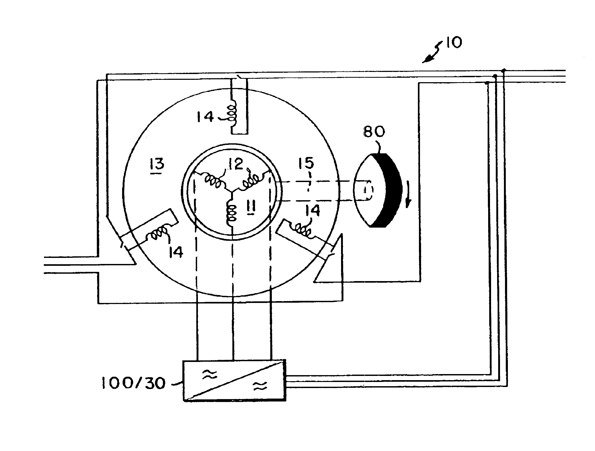
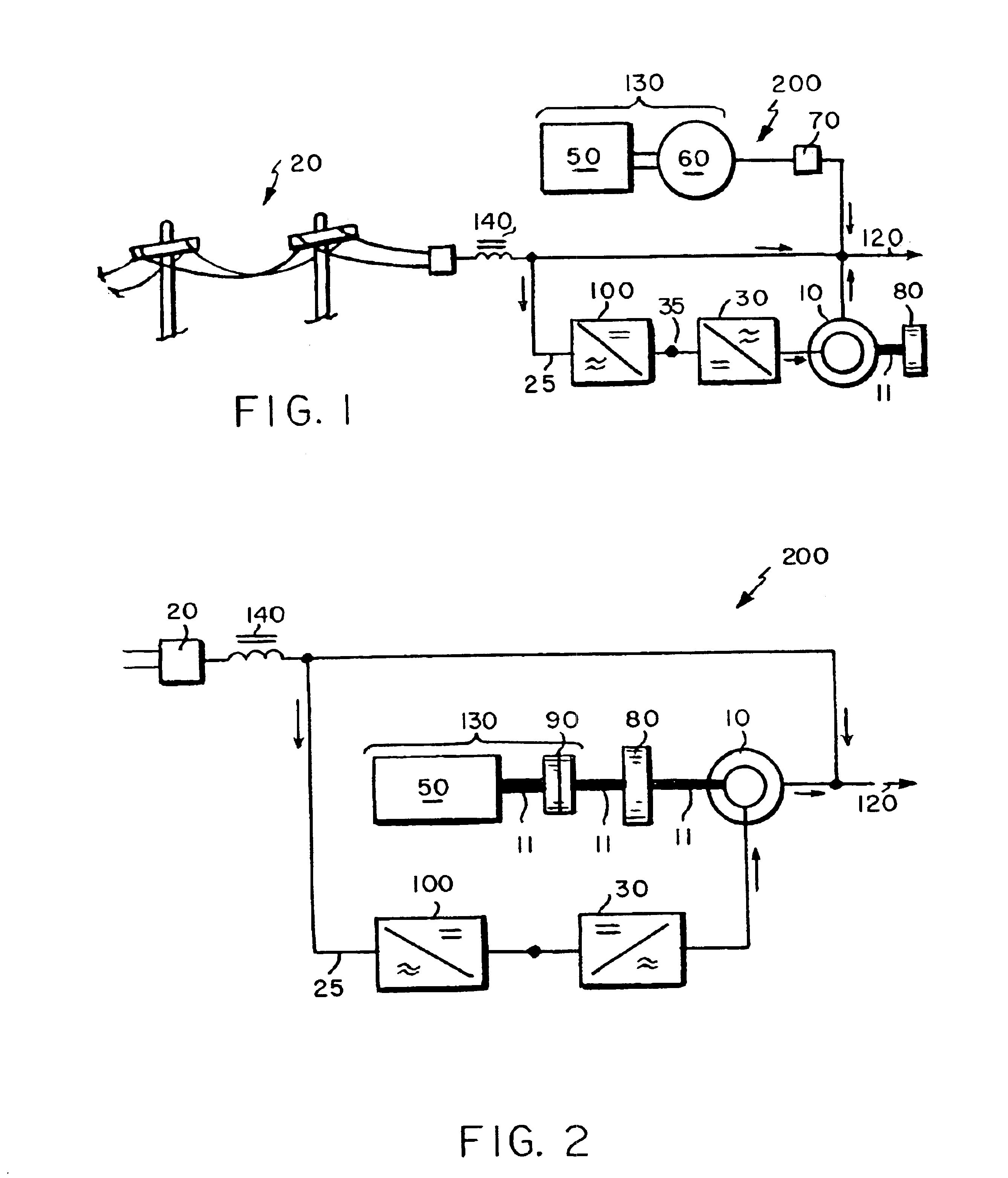
[0034]A first embodiment of a UPS system 200 in accordance with this invention is shown illustratively in FIG. 1. The embodied system 200 comprises three major components: a back-up power source 130, which, for illustrative purposes only, is shown as an engine 50 and generator 60; a slip-ring, or wound-rotor induction machine 10 and flywheel assembly 80 in combination, and a primary power source 20, e.g., a utility grid. As shown, the three components of the system 20 are in parallel. The primary power source 20 supplies alternating current (“AC”) and voltage (power) to the load 120 during normal operation. “Normal operation” is defined herein as referring to those periods of operation during which the primary power source 20 is providing power to the load 120 without any sags or dips of sufficient magnitude as to cause, e.g., motors to trip or computers to shutdown.

[0035]If and when the primary power source 20 fails, which is to say that power levels dip or sag below normal operati...


PUM


Abstract

Several embodiments of an uninterruptible power supply (UPS) system, which system provides highly reliable output power to a load using a slip-ring induction machine and a flywheel combination, are disclosed as well as methods relating thereto. In a preferred embodiment, the UPS system comprises a back-up power source, e.g., an engine and generator, and a slip-ring, or wound-rotor, induction motor and flywheel combination, which are in parallel to a primary power source, e.g., a utility grid. During normal operation of the UPS, the primary power source supplies alternating current and voltage to the load and the UPS compensates for voltage drop across the isolating inductor. Moreover, the primary power source keeps the slip-ring induction machine and flywheel in an excited state, i.e., the rotor of the slip-ring induction machine, the shaft of which is shared by the flywheel, is excited above normal synchronous speed. When the primary power source fails, the flywheel, which is rotating at super-synchronous speed and storing kinetic energy, drives the rotor of the slip-ring induction machine and generates, i.e., induces current in the stator. Accordingly, the flywheel and slip-ring induction machine combination provides instantaneous, short term power to the load until the back-up power source has powered up and been brought on line.

Description

CROSS REFERENCE OR RELATED APPLICATIONS[0001]This application claims the benefit of U.S. Provisional Application No. 60 / 265,216 filed Jan. 31, 2001.BACKGROUND OF THE INVENTION[0002]1. Field of the Invention[0003]The present invention relates to power supply systems, and, more particularly to uninterruptible power supply systems that provide highly reliable output power to a load using a slip-ring, wound-rotor type induction machine and flywheel assembly combination and a corresponding method for providing an uninterruptible power supply using the same.[0004]2. Background Art[0005]An uninterruptible power supply (“UPS”) system typically comprises a primary power source, e.g., a utility grid, in combination with one or more means for providing standby alternating current (“AC”) power in the event of a power failure, dips, sags, and the like of the primary power source. Conventional UPS systems typically comprise a primary power source 20 in combination with an engine 50 and generator ...

Claims


Application Information

Patent Timeline
Patent Type & Authority Patents(United States)
IPC IPC(8): H02J7/00H02J9/08
CPCH02J9/08
Inventor EISENHAURE, DAVID B.KIRTLEY, JR., JAMES L.LESSTER, LABAN EDWARD
Owner PERFECT GALAXY INT
Why Eureka
Try Eureka