Electronic pulse generation device

a generation device and pulse technology, applied in pulse train generators, tubes with screens, instruments, etc., can solve the problems of merely tens of thousands of electrons, complex panel fabrication process, and high panel fabrication cost, and achieve easy control of the number of electrons emitted.

Inactive Publication Date: 2006-07-04
NGK INSULATORS LTD
View PDF71 Cites 15 Cited by
  • Summary
  • Abstract
  • Description
  • Claims
  • Application Information

AI Technical Summary

Benefits of technology

[0010]The present invention has been made to solve the above problems, and an object of which is to provide an electronic pulse generation device made of a di

Problems solved by technology

All of these disclosed devices are disadvantageous in that since no dielectric material is employed in the emitter element, a forming process or a micromachining process is required between facing electrodes, a high voltage needs to be applied between the electrodes to emit electrons, and a panel fabrication process is complex and entails a high panel fabrication co

Method used


Image

  • Electronic pulse generation device
  • Electronic pulse generation device
  • Electronic pulse generation device

Examples


first embodiment

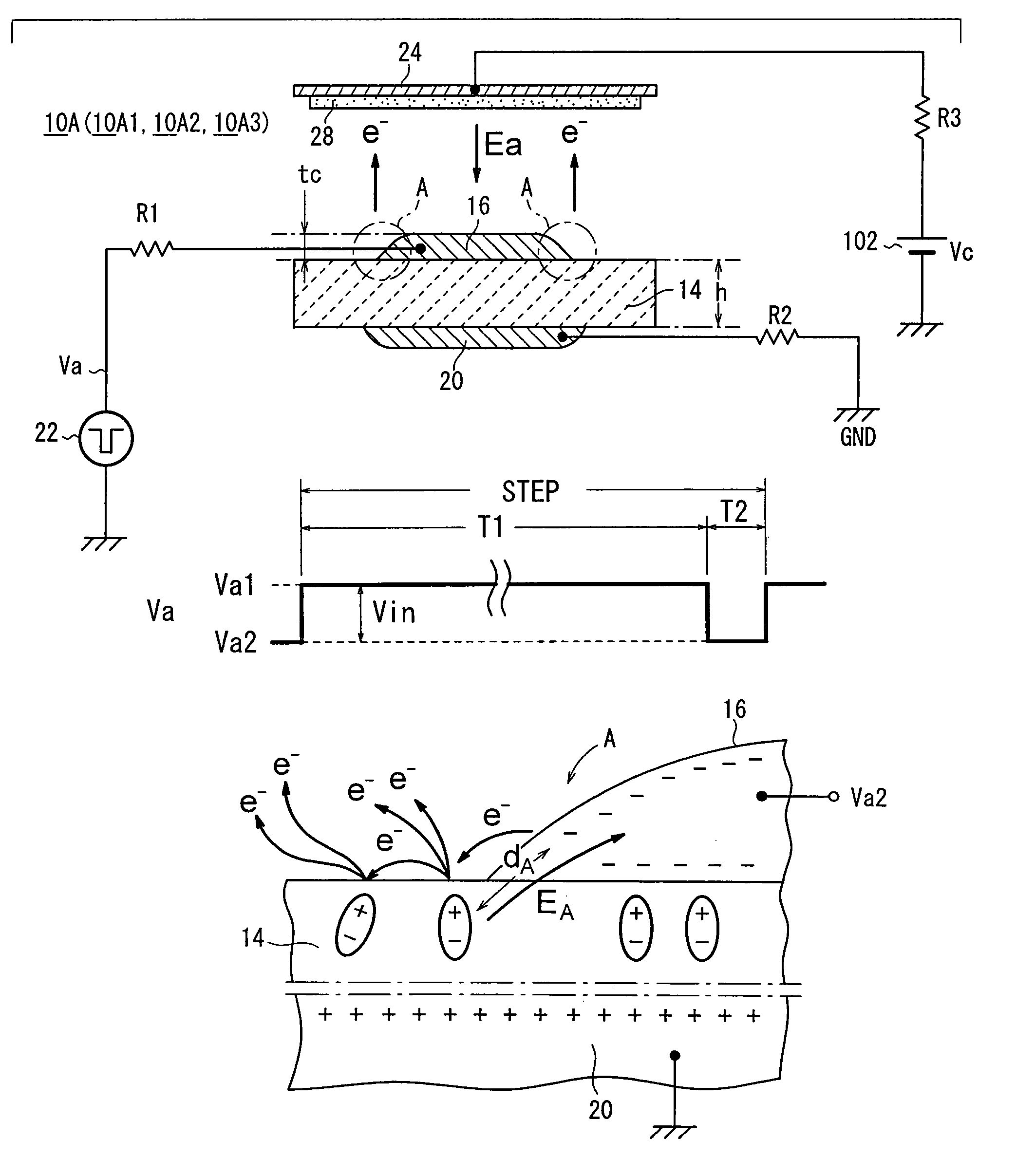
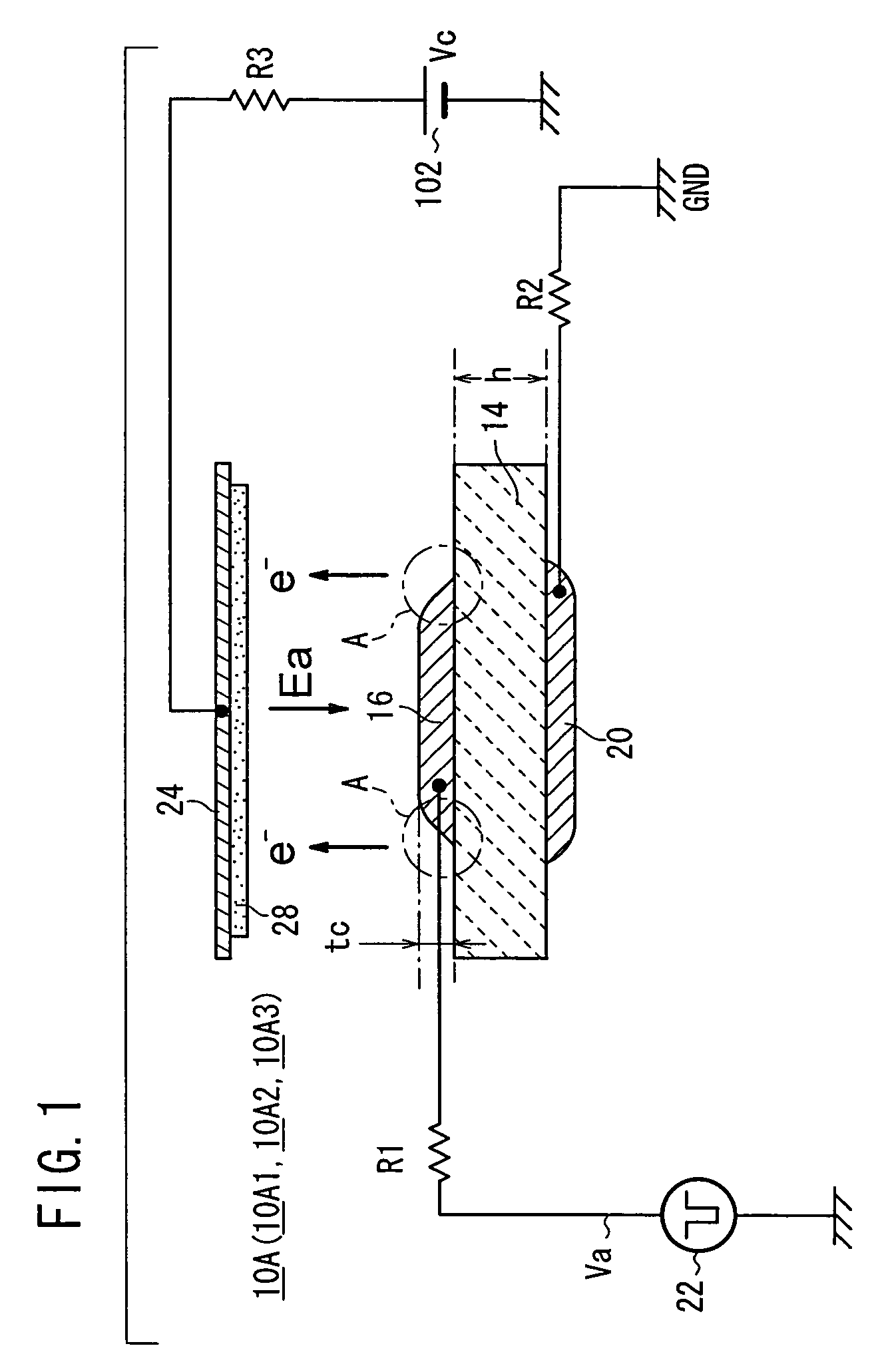
[0066]As shown in FIG. 1, an electronic pulse generation device 10A according to the present invention has an emitter section (emitter element) 14 having a plate shape, a first electrode (a cathode electrode) 16 formed on a front surface of the emitter section 14, a second electrode (an anode electrode) 20 formed on a back surface of the emitter section 14, and a pulse generation source (means for applying alternating pulse) 22 which applies a drive voltage Va between the cathode electrode 16 and the anode electrode 20 through a resistor R1.

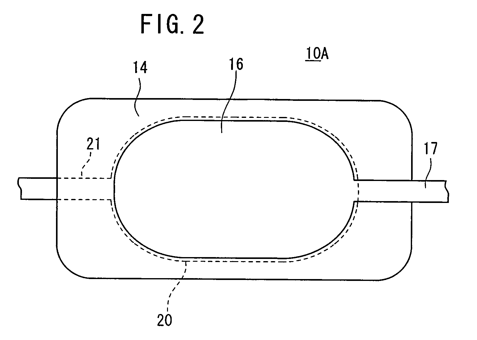
[0067]In an example shown in FIG. 1, the anode electrode 20 is connected to GND (ground) and hence set to a zero potential. However, the anode electrode 20 may be set to a potential other than the zero potential. As shown in FIG. 2, the drive voltage Va is applied between the cathode electrode 16 and the anode electrode 20 through a lead electrode 17 extending from the cathode electrode 16 and a lead electrode 21 extending from the anode electrod...

second embodiment

[0160]Next, an electronic pulse generation device 10B will be described with reference to FIG. 19.

[0161]As shown in FIG. 19, the electronic pulse generation device 10B according to the second embodiment has substantially the same structure as the electronic pulse generation device 10A according to the first embodiment, but differs from the electronic pulse generation device 10A in that the electronic pulse generation device 10B includes one substrate 12, an anode electrode 20 is formed on the substrate 12, the emitter section 14 is formed on the substrate 12 to cover the anode electrode 20, and the cathode electrode 16 is formed on the emitter section 14.

[0162]As with the electronic pulse generation device 10A according to the first embodiment, the electronic pulse generation device 10B can prevent the damages of the cathode electrode 16 by the positive ions, and has a long service life.

[0163]The emitter section 14 may be formed on the substrate 12 by any of various thick-film form...

third embodiment

[0175]Next, an electronic pulse generation device 10C will be described with reference to FIGS. 20 through 24B.

[0176]The electronic pulse generation device 10B according to the second embodiment has substantially the same structure as the electronic pulse generation device 10A according to the first embodiment described above, but differs from the electronic pulse generation device 10A in that both the cathode electrode 16 and the anode electrode 20 are disposed on one surface of the emitter section 14, with a slit 18 defined between the cathode electrode 16 and the anode electrode 20, the emitter section 14 being partly exposed through said slit 18.

[0177]As shown in FIG. 20, the electronic pulse generation device 10C has electric field concentration points A, B. The point A can also be defined as a triple point where the cathode electrode 16, the emitter section 14, and a vacuum are present at one point. The point B can also be defined as a triple point where the anode electrode 2...


PUM


Abstract

An electronic pulse generation device has an emitter section having a plate shape, a cathode electrode formed on a front surface of the emitter section, an anode electrode formed on a back surface of the emitter section, and a pulse generation source which applies a drive voltage between the cathode electrode and the anode electrode through a resistor. The anode electrode is connected to GND through another resistor. A collector electrode is provided above the cathode electrode, and the collector electrode is coated with a phosphor layer. A bias voltage is applied to the collector electrode through another resistor.

Description

[0001]This application claims the benefit of Japanese Application 2002-348900, filed Nov. 29, 2002, Japanese Application 2002-348908, filed Nov. 29, 2002, Japanese Application 2002-348916, filed Nov. 29, 2002, and Japanese Application 2003-155773, filed May 30, 2003, the entireties of which are incorporated herein by reference.BACKGROUND OF THE INVENTION[0002]1. Field of the Invention[0003]The present invention relates to an electronic pulse generation device having a first electrode and a second electrode formed on an emitter element.[0004]2. Description of the Related Art[0005]In recent years, electronic pulse generation devices have electron emitters which have a cathode electrode and an anode electrode as a basic device. The electronic pulse generation devices have been used in various applications such as field emission displays (FEDs) and backlight units. When the electronic pulse generation devices are applied as the FEDS, a plurality of electron emitters are arranged in a tw...

Claims


Application Information

Patent Timeline
IPC IPC(8): G09G3/10H01J29/04H01J1/30H01J1/312H01J1/32H01J31/12
CPCB82Y10/00H01J1/32H01J1/312H01J1/30
Inventor TAKEUCHI, YUKIHISANANATAKI, TSUTOMUOHWADA, IWAO
Owner NGK INSULATORS LTD
Why Eureka
Try Eureka