Magnetic resonance imaging apparatus

a magnetic resonance imaging and apparatus technology, applied in the direction of instruments, magnetic measurements, measurement devices, etc., to achieve the effect of excellent effect of reducing noise and other adverse effects of vibration

Inactive Publication Date: 2006-07-04
TOSHIBA MEDICAL SYST CORP
View PDF41 Cites 34 Cited by
  • Summary
  • Abstract
  • Description
  • Claims
  • Application Information

AI Technical Summary

Benefits of technology

[0008]It is an object of the present invention to provide a magnetic resonance imaging apparatus which has an excellent effect of reducing noise and other adverse effects of vibrations.

Problems solved by technology

The vibrations cause noise.

Method used


Image

  • Magnetic resonance imaging apparatus
  • Magnetic resonance imaging apparatus
  • Magnetic resonance imaging apparatus

Examples


embodiment 1

(Embodiment 1)

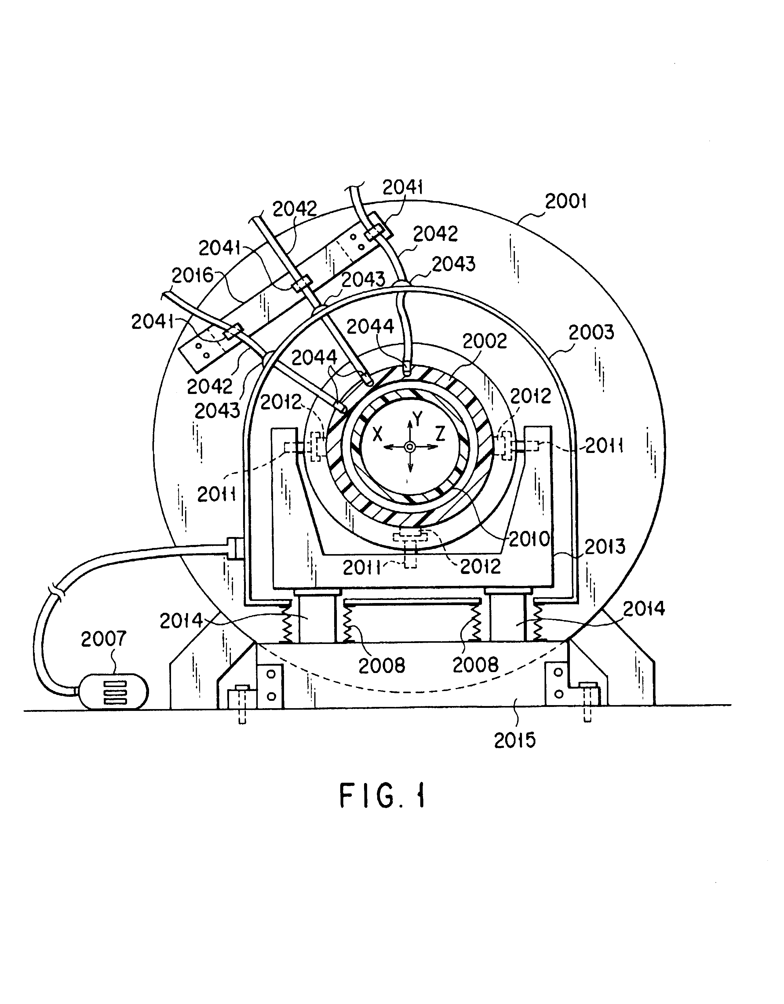
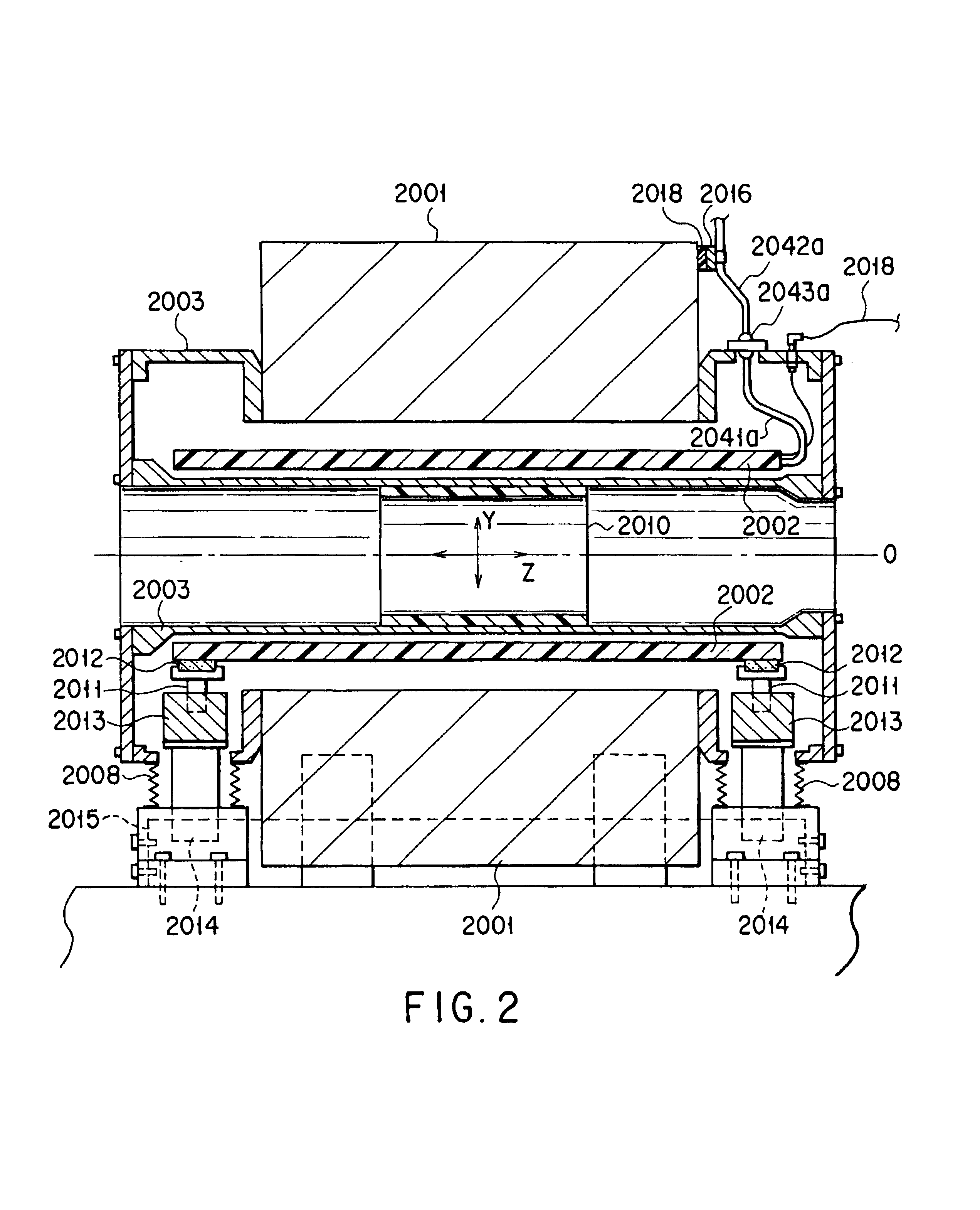
[0073]FIG. 1 is a view showing the internal arrangement of the gantry of a magnetic resonance imaging apparatus according to Embodiment 1. FIG. 2 is a longitudinal sectional view of FIG. 1. A substantially cylindrical static field magnet 2001 is comprised of, for example, a superconductive coil that is set in a superconductive state at an extremely low temperature and generates a homogenous static field and a cryostat for maintaining the extremely low temperature state of the superconductive coil. For the sake of convenience, three orthogonal axes (X-, Y-, and Z-axes) are defined with the central axis of the static field magnet 2001 being regarded as the Z-axis.

[0074]A substantially cylindrical gradient field coil 2002 is placed inside the static field magnet 2001. The gradient field coil 2002 is an ASGC (Actively Shielded Gradient Coil). The actively shielded gradient coil 2002 is made up of a main coil for generating a gradient field and an active shield coil which i...

embodiment 2

(Embodiment 2)

[0095]Problems in the prior art which are solved by Embodiment 2 will be described first.

[0096]As shown in FIG. 5, an air-core portion (imaging space) H is formed in a gantry G of an MRI apparatus. A main magnet 3003 for forming a strong static field, a whole body high-frequency coil 3004 for generating an RF magnetic field, and a gradient field coil 3005 are arranged in this air-core portion H, with its central axis L serving as a co-axis. In imaging operation, an object P to be examined is placed on the bed and inserted into the air-core portion H. A compact RF coil is sometimes mounted on the top independently of the whole body high-frequency coil 3004 to observe a small region such as the elbow or knee of the object P. This compact RF coil can be configured for reception only or both transmission and reception.

[0097]In an MRI apparatus having such an arrangement, de-coupling must be performed between the compact RF coil and the whole body high-frequency coil 3004. ...

embodiment 3

(Embodiment 3)

[0142]The problem to be solved by Embodiment 3 will be described first.

[0143]As a gradient field coil, a shield type coil assembly having a shield coil for suppressing a magnetic field that leaks out is frequently used. As an example of this coil, an ASGC (Actively Shielded Gradient Coil) is known. An ASGC is disclosed in U.S. Pat. Nos. 4,733,189 and 4,737,716. The ASGC has coil assemblies for the generation of magnetic fields corresponding to the X, Y, and Z channels of the MRI apparatus. Each coil assembly has a main coil and shield coil, thus realizing a shield structure for each channel in which a gradient field hardly leaks out.

[0144]In an MRI apparatus having a conventional shield type gradient field coil, e.g., an ASGC, a leak flux from the ASGC is magnetically coupled to a metal cover located inside a bore forming a diagnosing opening portion (worm bore) and covering a static field magnet to generate an eddy current on the cover. This causes noise. That is, the...


PUM


Abstract

A magnetic resonance imaging apparatus generates an MR signal from an object to be examined by applying a gradient field pulse generated by a gradient field coil and a high-frequency magnetic field pulse generated by a high-frequency coil to the object in a static field generated by a static field magnet, and reconstructs an image on the basis of the MR signal. The gradient field coil is housed in a sealed vessel. Numerous techniques are disclosed to reduce adverse effects of vibrations caused by rapidly changing gradient coil currents. By judicious use of non-conducting connection components between gantry components at some joint portions requiring electrical contact and at some other portions not requiring electrical contact, the generation of adverse B waves, and/or induced electron flow in response to physical vibration between joint components can be reduced.

Description

CROSS REFERENCE TO RELATED APPLICATIONS[0001]This is a division of commonly assigned application Ser. No. 09 / 764,221 filed Jan. 19, 2001 now U.S. Pat. No. 6,556,012 (now allowed). This application is also related to commonly assigned application Ser. No. 09 / 764,214 filed Jan. 19, 2001 and Ser. No. 09 / 764,215 filed Jan. 19, 2001.BACKGROUND OF THE INVENTION[0002]The present invention relates to a magnetic resonance imaging apparatus for generating a magnetic resonance signal (MR signal) by applying a gradient field pulse and high-frequency magnetic field pulse to an object to be examined which is placed in a homogeneous static field, and generating a magnetic resonance image (MR image) on the basis of this MR signal.[0003]In general, a magnetic resonance imaging apparatus of this type includes a static field magnet for generating a static field, a gradient field coil for generating a gradient field, and an RF coil for generating a high-frequency (RF) magnetic field pulse. An object to...

Claims


Application Information

Patent Timeline
Patent Type & Authority Patents(United States)
IPC IPC(8): G01V3/00G01R33/385
CPCG01R33/3854
Inventor YASUHARA, YASUTAKE
Owner TOSHIBA MEDICAL SYST CORP
Why Eureka
Try Eureka