
Relative intensity noise (RIN) reduction in fiber-based raman amplifier systems

a technology of relative intensity noise and amplifier system, which is applied in the field oframan fiber amplifier, can solve the problems of high relative intensity noise (rin) level, inability to provide such power, and excessive rin transfer from the pump to the signal, etc., and achieve the effect of reducing the effect of relative intensity noise (rin)

Active Publication Date: 2006-07-04
FURAKAWA ELECTRIC NORTH AMERICA INC
View PDF20 Cites 0 Cited by
  • Summary
  • Abstract
  • Description
  • Claims
  • Application Information

AI Technical Summary

Benefits of technology

[0005]The need remaining in the art is addressed by the present invention, which relates to Raman fiber amplifiers and, more particularly, to a technique for reducing the effects of relative intensity noise (RIN) associated with a pump source in a Raman amplifier arrangement.
[0006]In accordance with the present invention, power fluctuations in a pump laser source are monitored and the fluctuation signal is applied as a portion of the bias current input to a low power semiconductor (seed) laser whose output power is thus intensity-modulated as a function of the pump power fluctuations. As a result, by controlling the power of the seed laser, the power fluctuations in the pump laser can be compensated, thus minimizing the presence of RIN and / or the transfer of RIN from the pump laser to the optical information signal.

Problems solved by technology

In most cases, conventional semiconductor lasers cannot provide such power, resulting in the use of Raman fiber lasers as pump sources in these higher order systems.
One problem with Raman fiber lasers is that they have been found to exhibit relative intensity noise (RIN) levels higher than those found in semiconductor laser diodes.
However, in a “co-pumped” Raman amplifier where the pump and message signals propagate in the same direction through the fiber amplifier, excessive levels of RIN transfer from the pump to the signal have been problematic.
In the co-pumped architecture, pump power fluctuations induce gain fluctuations at the signal laser wavelength, resulting in a transfer of noise from the pump to the signal.
This degrades the optical signal-to-noise ratio (OSNR) of the optical information signal and the performance of the data link.

Method used


Image

  • Relative intensity noise (RIN) reduction in fiber-based raman amplifier systems
  • Relative intensity noise (RIN) reduction in fiber-based raman amplifier systems
  • Relative intensity noise (RIN) reduction in fiber-based raman amplifier systems

Examples


Embodiment Construction

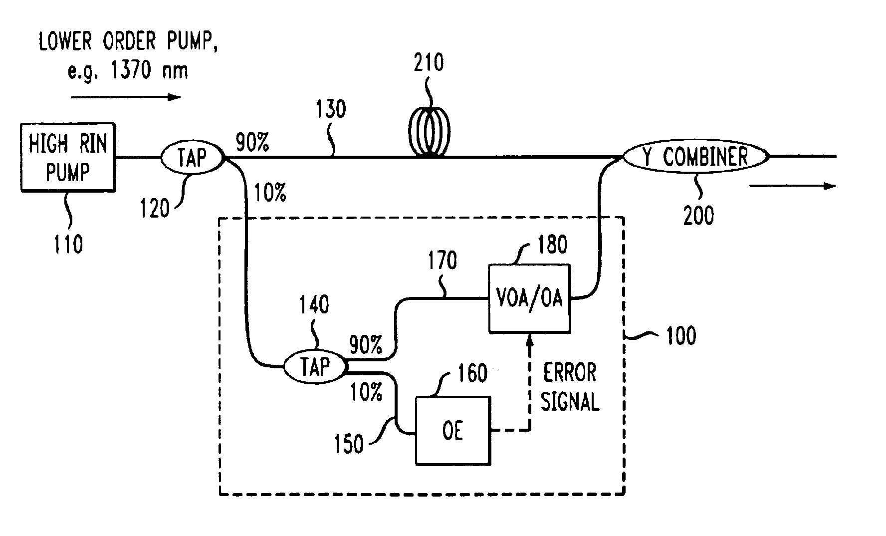
[0030]An exemplary second-order co-pumping Raman fiber amplifier 10 formed in accordance with the present invention is illustrated in FIG. 1. As shown, amplifier 10 comprises a first optical fiber signal path 12, where the optical information signal I is applied as an input to first fiber signal path 12. A Raman fiber laser 14 is used to provide the high power, second order pump signal R for this arrangement. It is to be understood that the use of a Raman fiber laser as a pump source is exemplary only, and various other sources may be used to supply the relatively high power pump signal required for a second-order (or third-order) system, where the principles of the present invention are equally applicable to any such arrangement. An optical tap 16 is used to remove a portion of the output from Raman fiber pump laser 14 and apply it as an input to a low power, first-order (seed) laser module 18. As will be discussed below in association with FIG. 3, in contrast to conventional secon...


PUM


Abstract

An arrangement for reducing the effects of pump signal relative intensity noise (RIN) in a Raman fiber amplifier. A portion of the output from a pump laser source is applied as an input to a compensating, lower power laser module, where fluctuations in the output power of the pump laser are used to control the bias current applied as an input to the compensating laser such that as the pump power increases, the bias current (and lower power laser output) decreases; conversely, as the pump power decreases, the bias current applied as an input to the compensating laser will be increased. The result is a relatively flat gain as seen by the information signal, thus minimizing the transfer of relative intensity noise from the pump to the signal.

Description

TECHNICAL FIELD[0001]The present invention relates to Raman fiber amplifiers and, more particularly, to a technique for reducing the effects of relative intensity noise (RIN) associated with a pump source in a Raman amplifier.BACKGROUND OF THE INVENTION[0002]Raman amplification is a technique well-known in the art for amplifying signal laser light in a fiber optic telecommunications data link. Three approaches to Raman amplification have been investigated to date, defined as “first order”, “second order” and “third order”. In first order Raman amplification, the pump and signal laser radiation are separated by a single Raman stokes shift. The pump and signal laser radiation in second and third order Raman amplification are separated by two and three Stokes shifts, respectively. These latter schemes require the use of “seed” lasers to provide a small amount of radiation in the intervening orders (e.g., in the first order for a second order system, or in the first and second orders fo...

Claims


Application Information

Patent Timeline
IPC IPC(8): H01S3/00H01S3/0941H01S3/30
CPCH01S3/302H01S3/09415
Inventor MERMELSTEIN, MARC D.
Owner FURAKAWA ELECTRIC NORTH AMERICA INC
Learn More