Cartridge locking mechanism for magnetic tape apparatus

Inactive Publication Date: 2006-07-04
NEC CORP
View PDF17 Cites 3 Cited by
  • Summary
  • Abstract
  • Description
  • Claims
  • Application Information

AI Technical Summary

Benefits of technology

[0013]It is an object of the present invention to provide a cartridge locking mechanism for a magnetic tape apparatus

Problems solved by technology

With the cartridge locking mechanism described above, however, particularly where an automatic loader is used to load and unload a medium, when the cartridge is r

Method used


Image

  • Cartridge locking mechanism for magnetic tape apparatus
  • Cartridge locking mechanism for magnetic tape apparatus
  • Cartridge locking mechanism for magnetic tape apparatus

Examples


Embodiment Construction

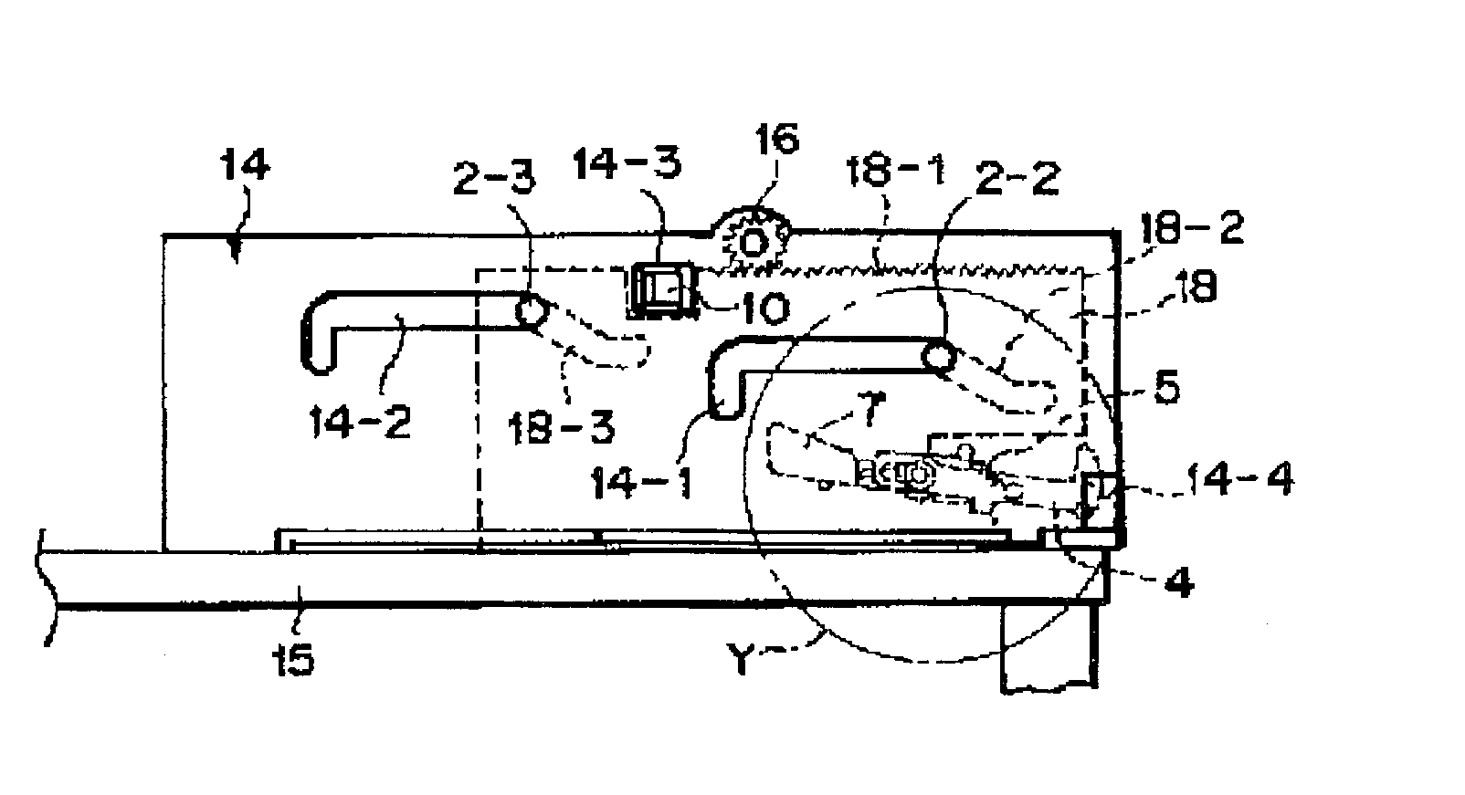
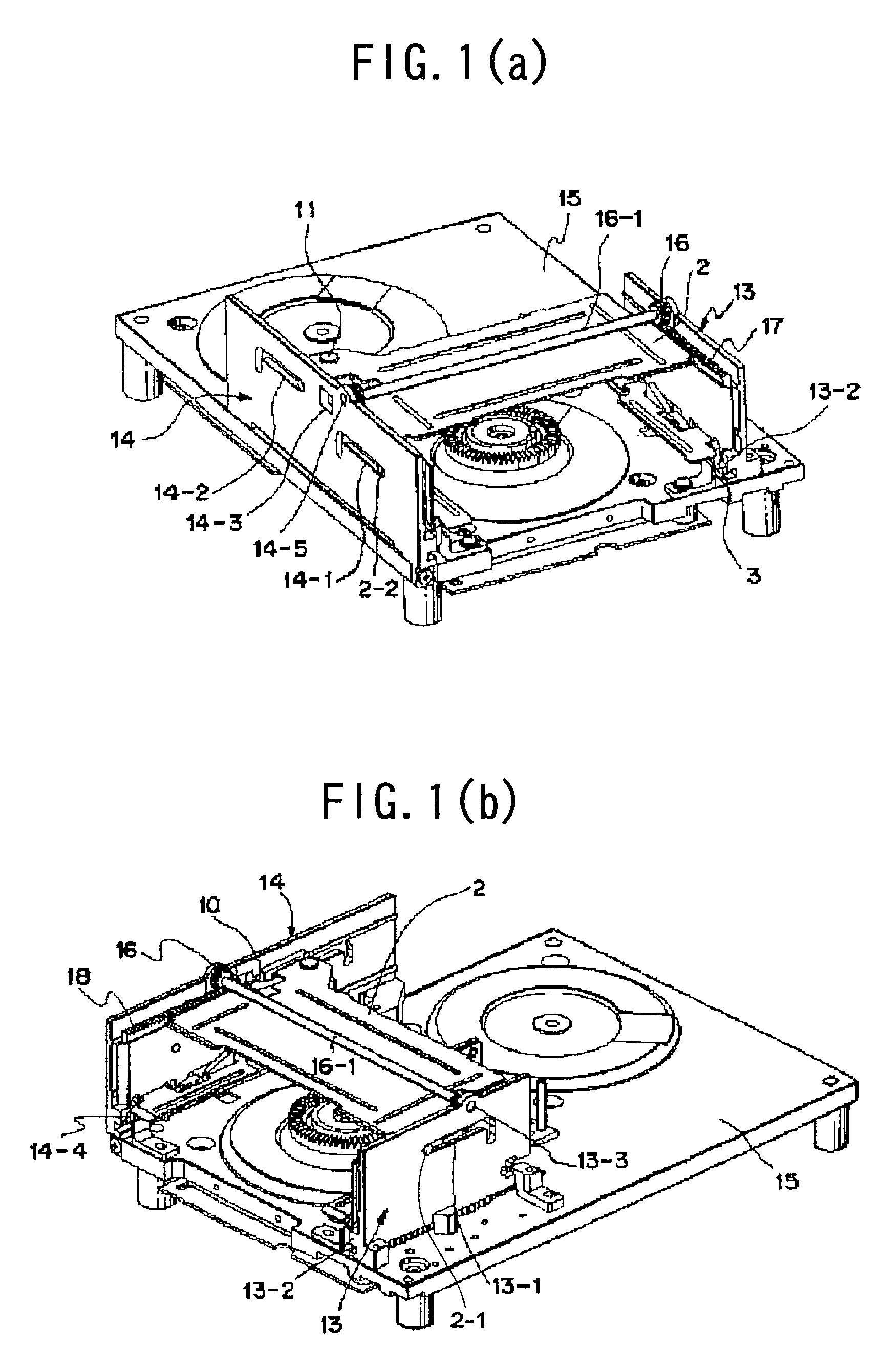
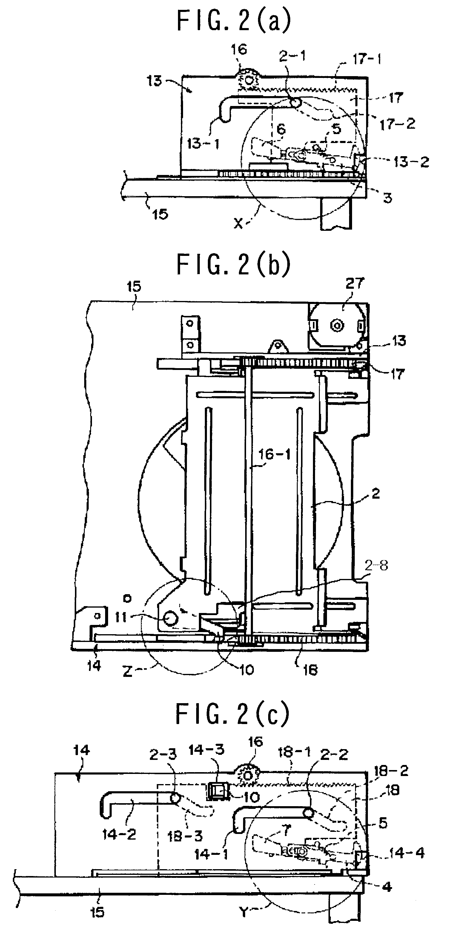
[0044]Referring to FIGS. 1(a) to 3(b), there is shown a cartridge locking mechanism for a magnetic tape apparatus to which the present invention is applied. The cartridge locking mechanism shown includes a right side plate 13 and a left side plate 14 extending uprightly in parallel to each other from the opposite left and right sides of a rectangular deck base 15, a right guide plate 17 and a left guide plate 18 mounted for movement and extending long the inner faces of the right side plate 13 and the left side plate 14, respectively, and a gate-shaped cartridge tray 2 inserted between the right guide plate 17 and the left guide plate 18. The cartridge locking mechanism has a substantially leftwardly and rightwardly symmetrical structure, and a cartridge 1 shown in FIGS. 4(a) to 4(c) is removably inserted into the cartridge tray 2.

[0045]As particularly seen in FIGS. 3(a) and 3(b), the cartridge tray 2 includes a top plate portion 2a, a pair of left and right side plate portions 2b a...


PUM


Abstract

A cartridge locking mechanism for a magnetic tape apparatus wherein variation of the pulling out force for a cartridge is prevented so that the cartridge can be removed smoothly is disclosed. A right guide plate and a left guide plate are provided for movement on the inner sides of a right side plate and a left side plate on the opposite sides of a deck base, respectively, and a cartridge tray is inserted in the inner sides of the right guide plate and the left guide plate. Aright locking lever and a cam lever, and a left locking lever and a cam lever for locking a cartridge are provided for rocking movement on pins provided at lower portions on the opposite sides of the cartridge tray each through a torsion spring and a torsion spring. A guide pin and a pair of pins are provided on side faces of the cartridge tray and fitted in guide slots in the right side plate and right guide plate and the left side plate and left guide plate, respectively, to guide the cartridge tray.

Description

BACKGROUND OF THE INVENTION[0001]1. Field of the Invention[0002]The present invention relates to a cartridge locking mechanism for locking a magnetic tape cartridge in a magnetic tape apparatus.[0003]2. Description of the Related Art[0004]In a magnetic tape apparatus, when a cartridge is inserted into a cartridge tray, it is necessary to lock the cartridge so that it may not come out of the cartridge tray, but when the cartridge is to be removed, it is necessary to unlock the cartridge so that the cartridge can be removed smoothly. It is demanded that a cartridge locking mechanism satisfy the two requirements just described.[0005]A cartridge locking mechanism of the type described is disclosed in Japanese Patent Laid-Open No. 2001-118305. The cartridge locking mechanism is shown in FIGS. 15(a), 15(b), 16, 17(a) and 17(b).[0006]Referring to FIGS. 15(a) to 17(b), the cartridge locking mechanism shown is so structured that it locks one of the opposite left and right sides of a cartridg...

Claims


Application Information

Patent Timeline
IPC IPC(8): G11B15/68G11B15/675
CPCG11B15/67547G11B15/675
Inventor TSUCHIYA, MANABU
Owner NEC CORP
Why Eureka
Try Eureka