
Method and apparatus for controlling network data congestion

a network data and congestion technology, applied in data switching networks, frequency-division multiplexes, instruments, etc., can solve problems such as exacerbating problems, affecting the performance of network data, and affecting the quality of network data, so as to minimize congestion and minimize congestion

Inactive Publication Date: 2006-07-04
STMICROELECTRONICS SRL
View PDF13 Cites 18 Cited by
  • Summary
  • Abstract
  • Description
  • Claims
  • Application Information

AI Technical Summary

Benefits of technology

[0016]It is therefore an object of the present invention to reduce congestion in a port receiver, such as with the receive FIFO memory of a network device, e.g., an HDLC controller, and reduce the chance of dropped frames.
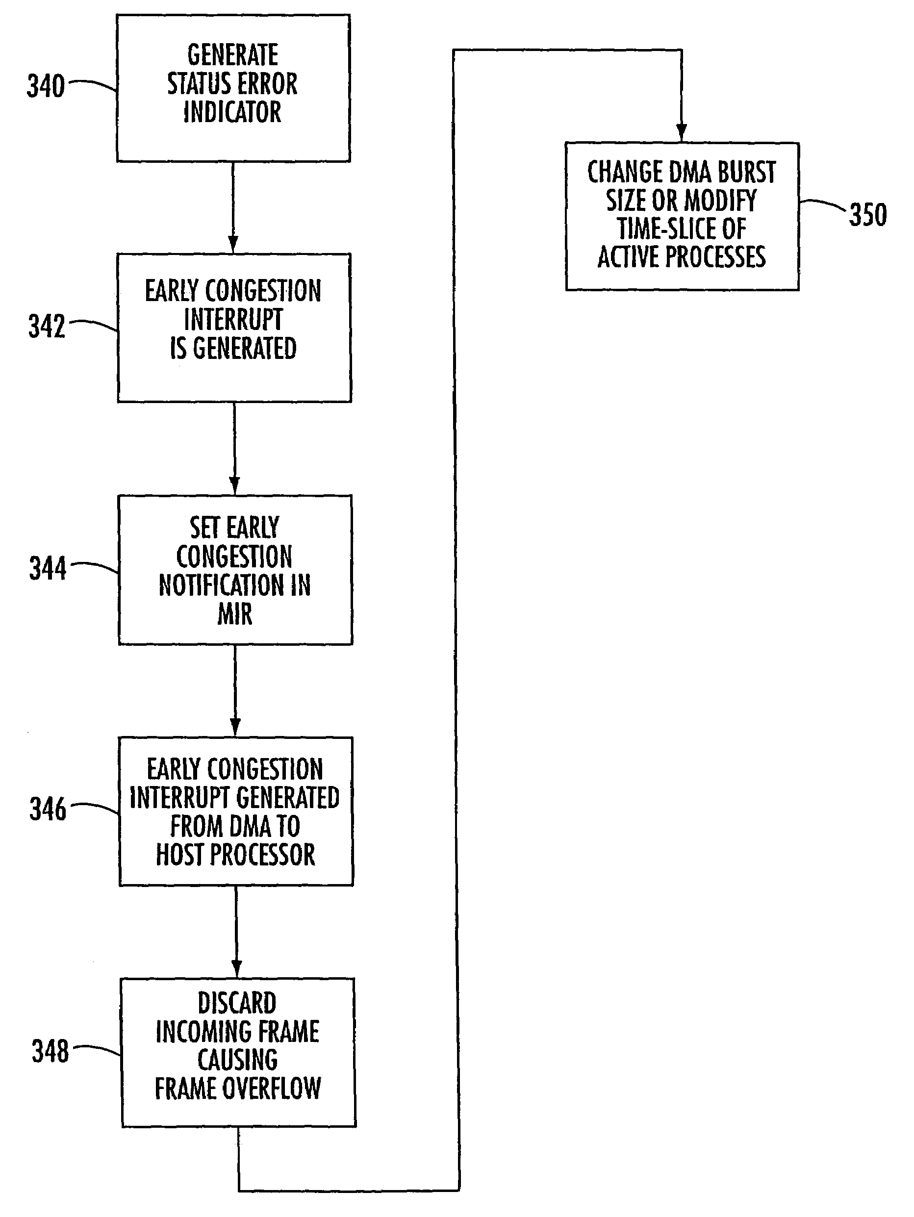
[0017]In accordance with the present invention, a status error indicator is now generated within a received FIFO memory of a network device, which is indicative of a frame overflow within the FIFO memory. This status error indicator can be read by a communications processor and an early congestion interrupt can be generated to a host processor indicative that a frame overflow has occurred within the receive FIFO memory. The incoming frame can be discarded and the services of received frames can be enhanced within the FIFO memory by one of either increasing the number of words of a direct memory access (DMA) unit burst size or modifying the time-slice or other active processes that are sharing the system.
[0018]In accordance with the present invention, a method controls the flow network data arranged in frames and minimizes congestion. The method comprises the step of generating a status error indicator within a receive FIFO memory indicative of a frame overflow within the FIFO memory. In response to the status error indicator, an early congestion interrupt can be generated to a host processor indicative that a frame overflow has occurred within the receive FIFO memory. The incoming frame that has caused the frame overflow can be discarded and the services of frames received within the FIFO memory can be enhanced by one of either increasing the number of words of a direct memory access (DMA) unit burst size or modifying the time-slice or other active processes.
[0020]An apparatus for controlling the flow network data arranged in frames and minimizing congestion is disclosed and includes a FIFO memory, including means for generating a status error indicator indicative of a frame overflow within the FIFO memory. A direct memory access unit has an interrupt register and early notification bits that are set in response to the status error indicator corresponding to the overflow within the FIFO memory. Means generates an early congestion interrupt from the direct memory access unit and a host processor receives the interrupt from the direct memory access unit. Means then generates instructions from the host processor to the FIFO memory to discard the incoming frame that has caused the frame overflow. The apparatus can further comprise a system bus connecting the direct memory access unit with the host processor on which the early congestion notification interrupt passes. The status error indicator could comprise a status error bit and a flip-flop could be set to indicate the status error bit. Additionally, means sets an overflow bit within the FIFO memory indicative of the overflow condition. A network device that controls flow of data arranged in frames and minimizes congestion is also disclosed.

Problems solved by technology

However, often bus latency occurs corresponding to the delay between the time the bus is requested and the time the bus is actually obtained to transfer data and frames.
Other peripheral circuits, such as a tape reader or CD ROM, could be used in the system, such as with a personal computer, and inherently cause greater latency.
At high speeds, such as T2 and T3 type frequencies, there could be much congestion causing an overflow.
Also, instead of a single downstream node with a loss frame problem, a situation could rapidly develop where many downstream nodes are forced to reclock the transmit windows, easily exacerbating the problem.
Although upper level software could retransmit any frames that are discarded, this would create greater congestion and take greater bandwidth.
This could all create greater problems.

Method used


Image

  • Method and apparatus for controlling network data congestion
  • Method and apparatus for controlling network data congestion
  • Method and apparatus for controlling network data congestion

Examples


Embodiment Construction

[0050]The present invention will now be described more fully hereinafter with reference to the accompanying drawings, in which preferred embodiments of the invention are shown. This invention may, however, be embodied in many different forms and should not be construed as limited to the embodiments set forth herein. Rather, these embodiments are provided so that this disclosure will be thorough and complete, and will fully convey the scope of the invention to those skilled in the art. Like numbers refer to like elements throughout.

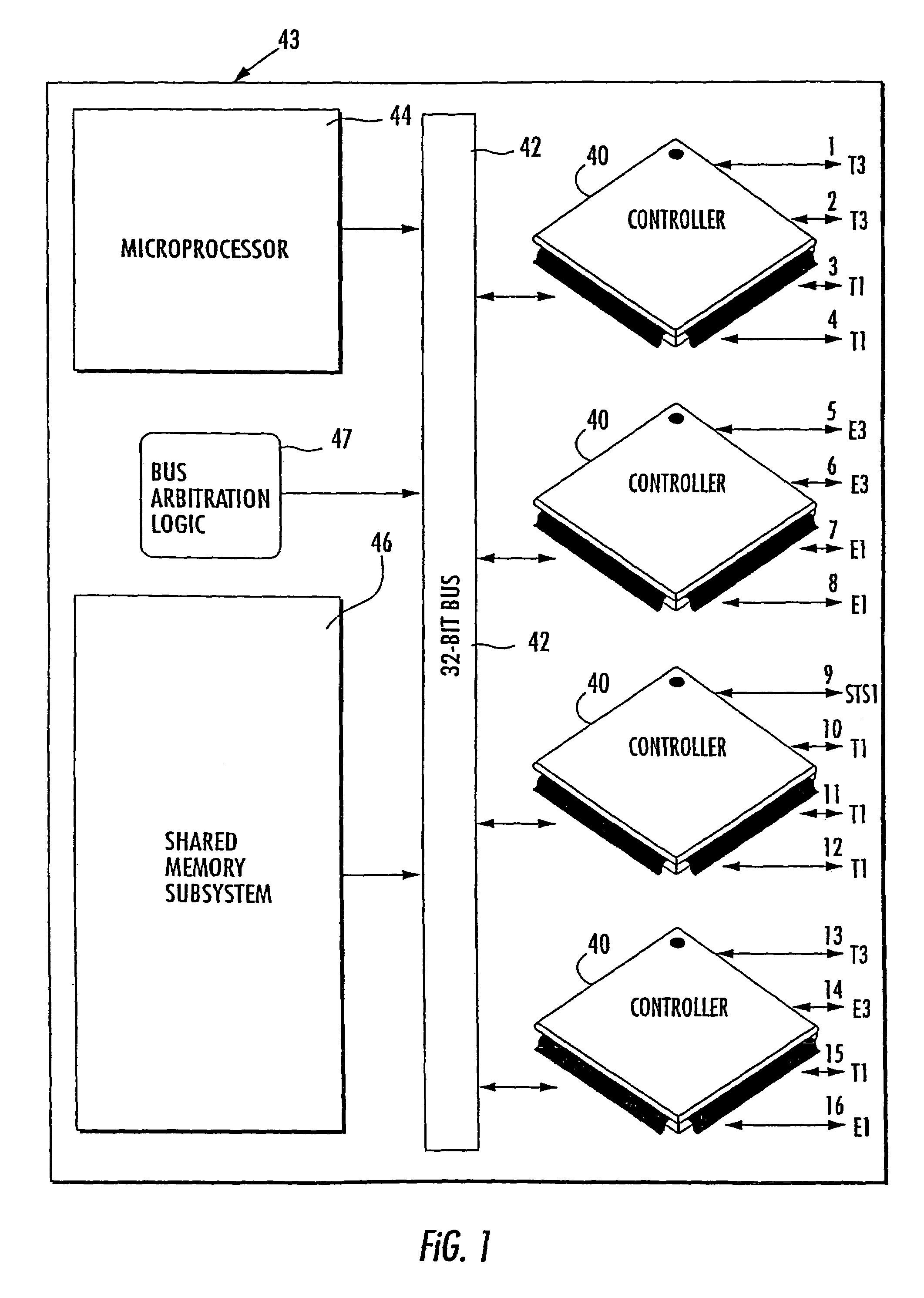
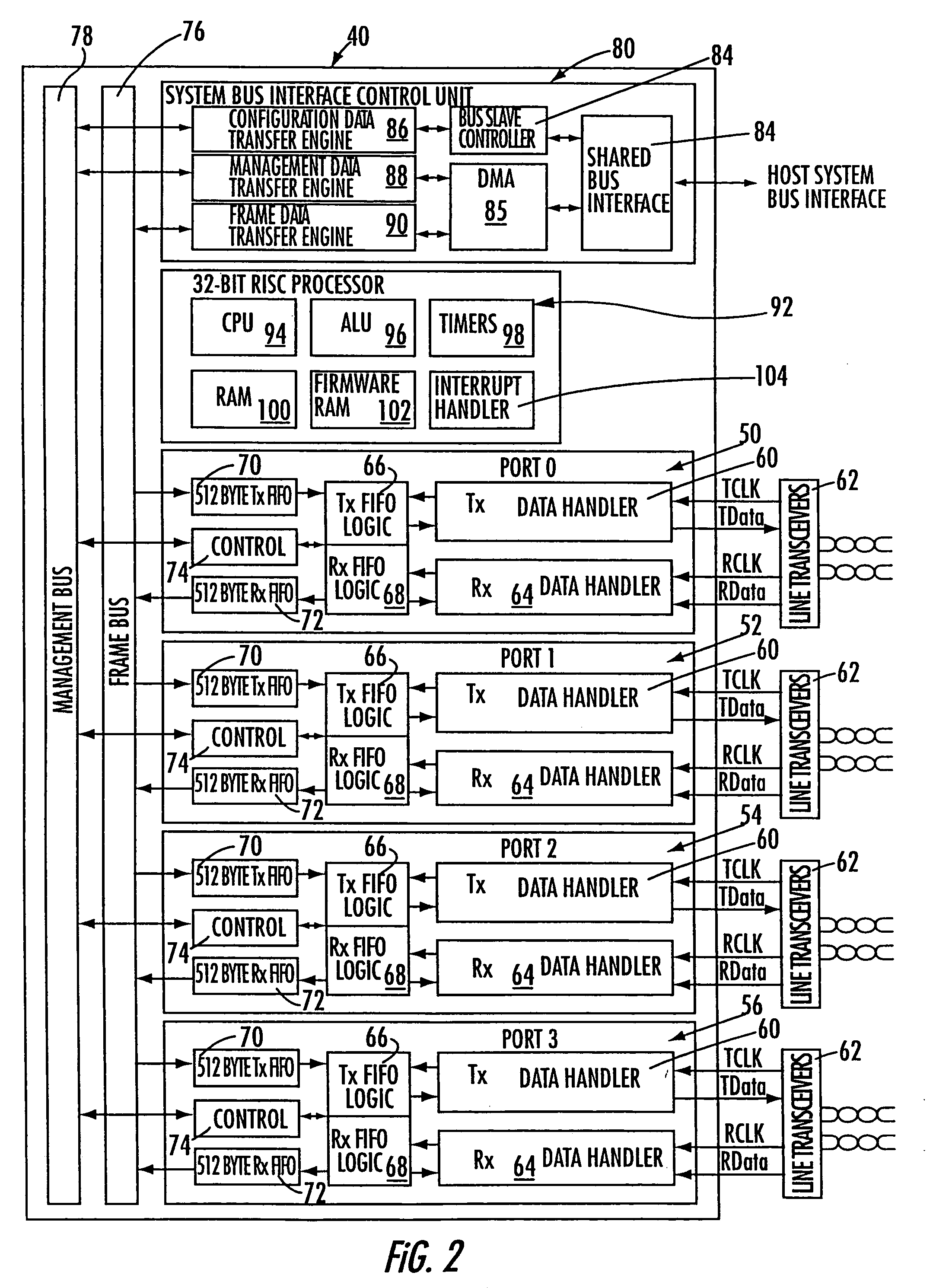
[0051]Referring now to FIGS. 1–3, and more particularly to FIGS. 1 and 2, there is illustrated a high level diagram of a network controller and host system that are exemplary of the present invention. The network controller is an HDLC controller in one specific embodiment of the invention.

[0052]The present invention can be used in a number of different networks, including a conventional network making use of network controllers. For example, the invention ...


PUM


Abstract

A method, apparatus and network device for controlling the flow of network data arranged in frames and minimizing congestion is disclosed. A status error indicator is generated within a receive FIFO memory indicative of a frame overflow within the receive FIFO memory. In response to the status error indicator, an early congestion interrupt is generated to a host processor indicative that a frame overflow has occurred within the receive FIFO memory. The incoming frame is discarded and the services of received frames are enhanced by one of either increasing the number of words of a direct memory access (DMA) unit burst size, or modifying the time-slice of other active processes.

Description

[0001]This application is a continuation of utility application Ser. No. 09 / 163,819 filed Sep. 30, 1998 now U.S. Pat. No. 6,717,910.FIELD OF THE INVENTION[0002]This patent application is related to a method and apparatus for controlling the flow of network data arranged in frames and minimizing congestion, and more particularly, controlling congestion in a network device, such as an HDLC controller, having a FIFO memory at each port.BACKGROUND OF THE INVENTION[0003]Data networks have become increasingly important in day-to-day activities and business applications. Most of these networks are a packet-switched network, such as the Internet, which uses a Transmission Control Protocol (TCP) and an Internet Protocol (IP), frequently referred to as TCP / IP. The Transmission Control Protocol manages the reliable reception and transmission of network traffic, while the Internet Protocol is responsible for routing to ensure that packets are sent to a correct destination.[0004]In a typical net...

Claims


Application Information

Patent Timeline
Patent Type & Authority Patents(United States)
IPC IPC(8): H04J1/16H04L13/08H04L12/56
CPCH04L47/10H04L47/12H04L49/9078H04L49/90H04L49/9068H04L47/30
Inventor KASPER, CHRISTIAN D.GURITZ, ELMER H.
Owner STMICROELECTRONICS SRL
Learn More