Delay locked loop fine tune

a delay and loop technology, applied in the direction of generating/distributing signals, instruments, pulse techniques, etc., can solve the problems of unsatisfactory level of accuracy of adjusting the delay by a delay stage of the delay line, affecting the timing relationship between external and internal clock signals, and unable to meet the requirements of the time. the effect of the timing relationship

Inactive Publication Date: 2006-07-04
ROUND ROCK RES LLC
View PDF15 Cites 64 Cited by
  • Summary
  • Abstract
  • Description
  • Claims
  • Application Information

AI Technical Summary

Benefits of technology

[0007]The present invention includes a DLL that generates an internal clock signal by delaying an external clock signal with a coarse delay and a fine delay. The coarse delay includes a number of coarse unit delays within a coarse delay range; the fine delay includes a number of fine unit delays within a fine delay range. A fine unit delay is smaller than a coarse unit delay. To keep the external and internal clock signals synchronized, the DLL adjusts the fine delay then the coarse delay by increasing or decreasing the numbers of fine unit delays and coarse unit delays. The coarse delay is adjusted only when the fine delay is at a minimum or maximum delay of the fine delay range and an increase or decrease in delay is needed respectively. Since the fine unit delay is smaller than the coarse unit delay, adjusting the fine delay before adjusting the coarse delay reduces the chance of overshoot or undershoot a target delay. Therefore, the accuracy of the timing relationship between external and internal clock signals is improved.

Problems solved by technology

In some cases, the internal signal may miss the window, i.e., overshoot or undershoot the target delay, and therefore a subsequent adjustment step is unnecessarily created.
Moreover, adjusting the delay by a delay stage of the delay line may not provide satisfactory level of accuracy especially if the DLL is used in new generations of high speed devices such as microprocessor and dynamic random access memory (DRAM) devices.

Method used


Image

  • Delay locked loop fine tune
  • Delay locked loop fine tune
  • Delay locked loop fine tune

Examples


Embodiment Construction

[0018]The following detailed description refers to the accompanying drawings which form a part hereof, and which is shown, by way of illustration specific embodiments in which the invention may be practiced. These embodiments are described in sufficient detail to enable those skilled in the art to practice the invention, and it is to be understood that other embodiments may be utilized and that logical, mechanical and electrical changes may be made without departing from the spirit and scope of the present invention. The following detailed description is, therefore, not to be taken in a limiting sense, and the scope of the invention is defined only by the appended claims.

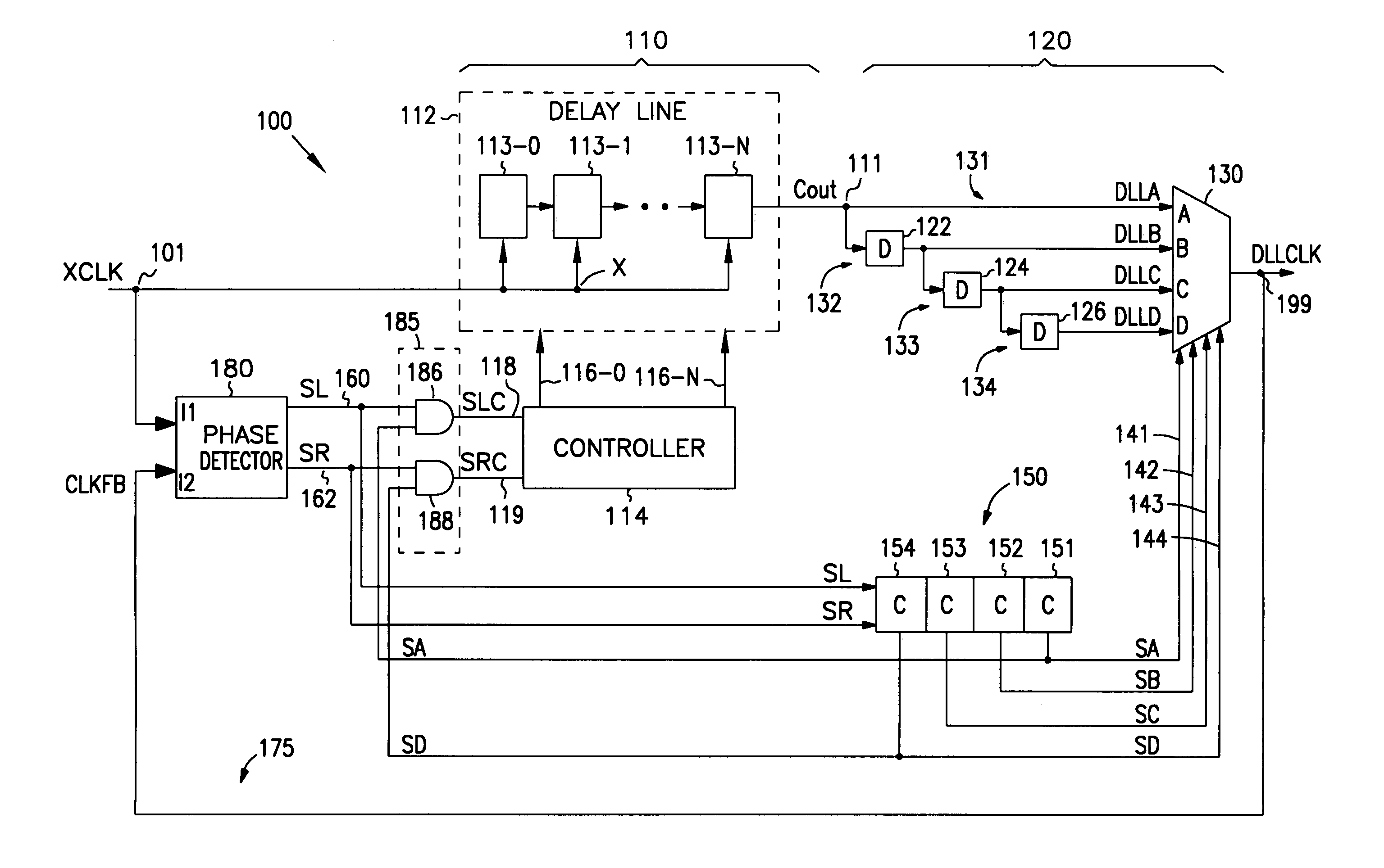
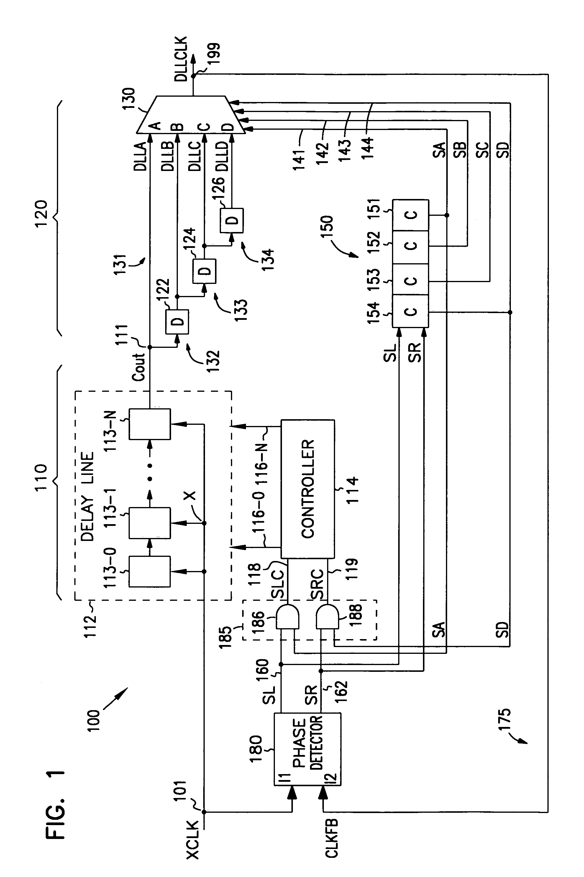
[0019]FIG. 1 is a diagram of a digital DLL 100 according to one embodiment of the invention. DLL 100 includes an input at node 101 and an output at node 199. Input 101 receives an external clock signal XCLK and output 199 provides an internal clock signal DLLCLK. DLL 100 also includes a coarse delay segment 110, a f...


PUM


Abstract

A digital delay locked loop (DLL) includes a coarse delay segment and fine delay segment. The coarse delay segment includes a coarse delay range. The fine delay segment includes a fine delay range. The coarse delay segment and the fine delay segment apply a coarse delay and a fine delay to an external clock signal to generate an internal clock signal. To keep the external and internal clock signals synchronized, the DLL adjusts the fine delay or coarse delay by increasing or decreasing the fine delay or the coarse delay. The coarse delay is adjusted only when the fine delay is at a minimum or maximum delay of the fine delay range and an increase or decrease in delay is needed respectively.

Description

[0001]This application is related to application Ser. No. 09 / 585,035, filed Jun. 1, 2000.TECHNICAL FIELD OF THE INVENTION[0002]The present invention relates to signal generation in integrated circuits, and in particular to signal generation using a delay locked loop.BACKGROUND OF THE INVENTION[0003]Delay locked loops (DLLs) are often used in integrated circuits (ICs) to generate an internal clock signal. The internal clock signal is generated by applying a delay to a system clock or an external clock signal. The DLL automatically adjusts the delay to keep the internal and external clock signals synchronized.[0004]A conventional DLL includes a delay line. The delay line includes a number of delay stages to apply an amount of delay to an external clock signal to generate an internal clock signal. A phase detector compares the phase difference between the external and internal clock signals. If the external and internal signals are not synchronized, the phase detector generates shiftin...

Claims


Application Information

Patent Timeline
Patent Type & Authority Patents(United States)
IPC IPC(8): H03L7/06H03D3/24H04L5/00H04L7/00H04L9/00G11C7/22H03K5/13H03L7/081H03L7/089
CPCG11C7/1066G11C7/22G11C7/222H03K5/133H03L7/089H03L7/0818H03L7/0814H03L7/0816
Inventor BELL, DEBRA M.
Owner ROUND ROCK RES LLC
Why Eureka
Try Eureka