Downhole tool

a tool and tool body technology, applied in earth drilling and mining, drilling machines and methods, construction, etc., can solve the problems of poor performance of the hammer, difficult control of fluid swirl, and easy to be damaged by the hammer

Inactive Publication Date: 2006-07-11
ROTECH GROUP
View PDF13 Cites 40 Cited by
  • Summary
  • Abstract
  • Description
  • Claims
  • Application Information

AI Technical Summary

Benefits of technology

[0012]This provides a downhole tool which may be used to generate a reciprocating mechanical load having many uses in the downhole environment, for example, as part of a drilling assembly to improve the rate and efficiency of drilling; to set tools or tool strings in a downhole environment by hammering the tool into place; to dislodge tools or tool strings which have become lodged downhole by exerting a hammer force on the tool; and for recovering or “fishing” tools which have become lodged downhole.
[0017]a first member, a second member and sealing means between said first and second members, wherein, in use, application of fluid pressure to the hammer causes the first and second members to move from respective first to respective second positions and during such movement the sealing means sealing between the first and second members substantially prevents fluid flow therebetween, and
[0028]a sealing assembly adapted to seal the tool to prevent fluid flow through the tool when the first and second members are in their respective first positions and to allow fluid flow through the tool when the first and second members are in their respective second positions;

Problems solved by technology

Such existing hammers tend to be either structurally very simple or very complicated, with a large number of co-operating moving parts.
However, this results in poor performance of the hammer and, the fluid swirl is difficult to control.
Disadvantages associated with structurally complex hammers include that the hammers are difficult and expensive to manufacture, assemble and maintain.

Method used


Image

  • Downhole tool
  • Downhole tool
  • Downhole tool

Examples


Embodiment Construction

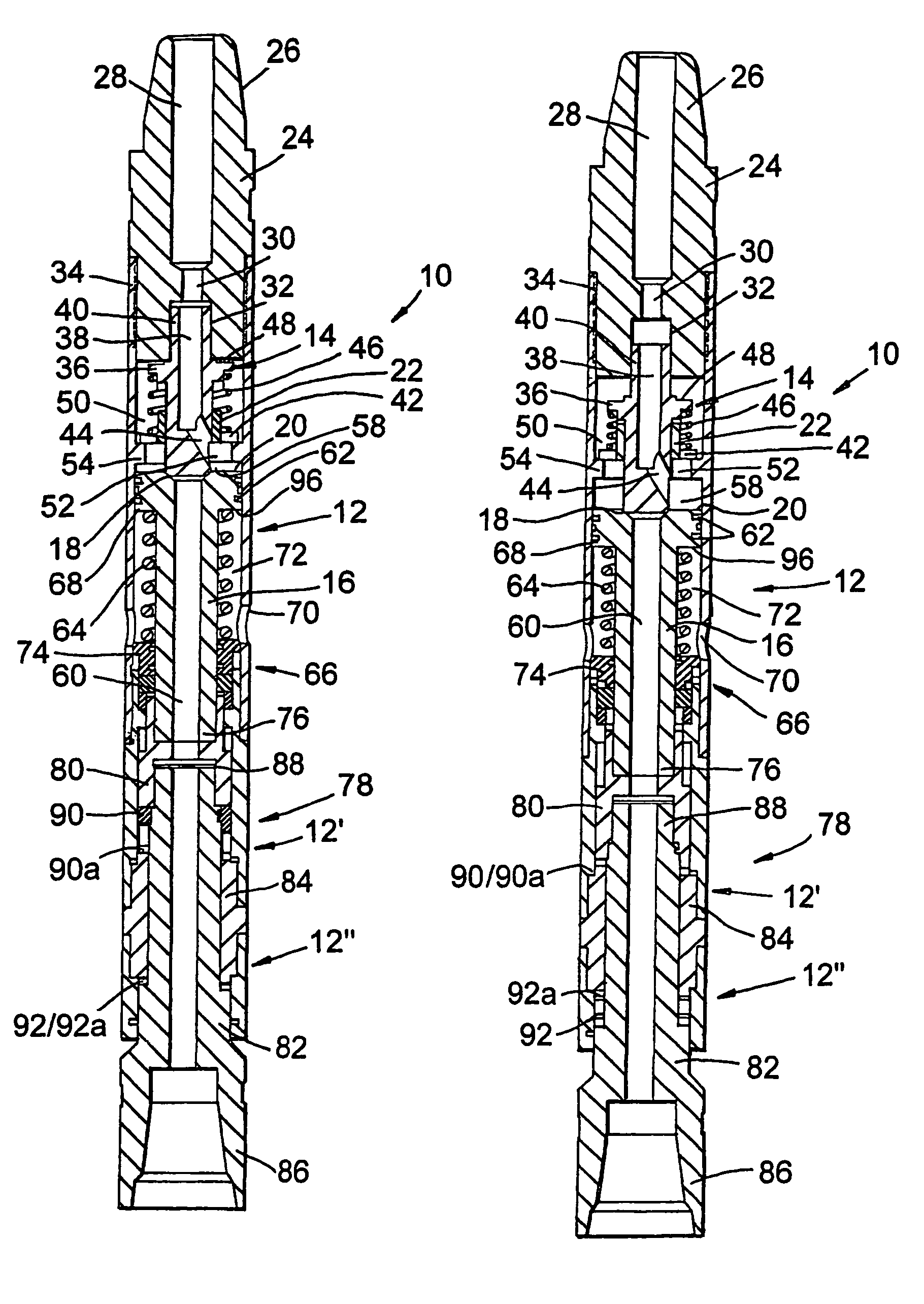
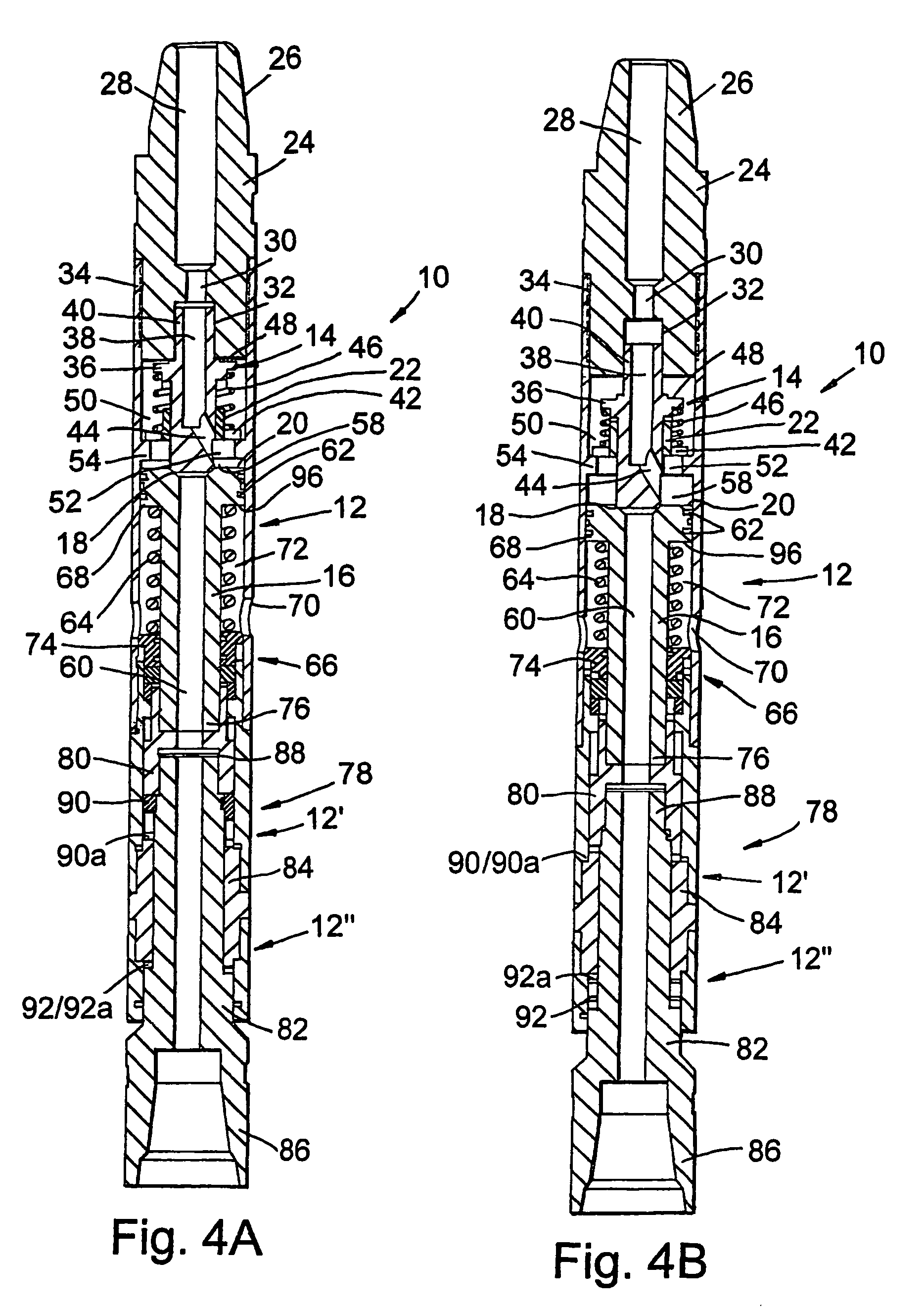
[0058]It will be understood that references herein to longitudinal movement are to movement generally in a direction of a main or longitudinal axis of the downhole tool.

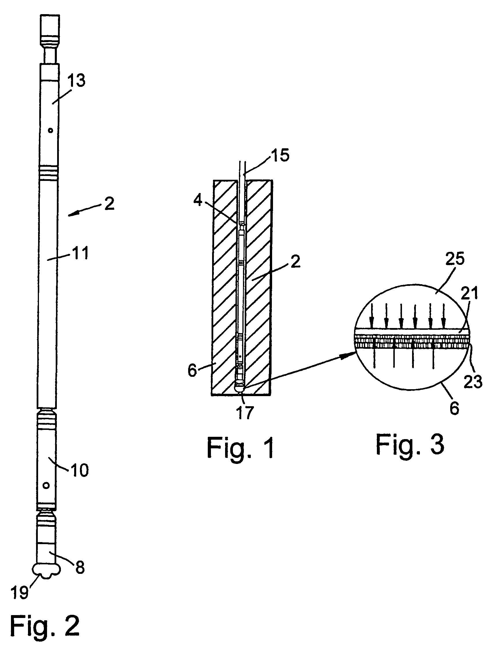
[0059]The invention provides a downhole tool which allows for a mechanical load to be generated downhole. It will be understood that references to a mechanical load are to a load generated by the tool which may be transmitted by, for example, a mechanical connection or coupling, to transmit the load to a secondary object or tool located downhole. It will further be understood that the mechanical load is preferably directed longitudinally through the tool and through a borehole in which the tool is located. In particular, the downhole tool comprises an impact hammer for use in downhole operations, which generates a mechanical load in the form of a percussive impact or a percussive pull force in response in part to fluid flowing through the tool.

[0060]The downhole tool may be provided as part of a drilling assembly inc...


PUM


Abstract

A downhole tool for generating a longitudinal mechanical load. In one embodiment, a downhole hammer is disclosed which is activated by applying a load on the hammer and supplying pressurizing fluid to the hammer. The hammer includes a shuttle valve and piston that are moveable between first and further position, seal faces of the shuttle valve and piston being released when the valve and the piston are in their respective further positions, to allow fluid flow through the tool. When the seal is releasing, the piston impacts a remainder of the tool to generate mechanical load. The mechanical load is cyclical by repeated movements of the shuttle valve and piston.

Description

CROSS-REFERENCE TO RELATED APPLICATIONS[0001]This application is a continuation of International application PCT / GB02 / 02381 filed May 20, 2002, the entire content of which is expressly incorporated herein by reference thereto.BACKGROUND ART[0002]The present invention relates to a downhole tool. In particular, but not exclusively, the present invention relates to a downhole tool for generating a longitudinal mechanical load.[0003]A variety of different downhole tools are used in the oil and gas exploration and production industry. Existing downhole tools used for generating longitudinally directed mechanical loads, such as impact hammers, are designed primarily for the installation and / or retrieval of downhole assemblies, for example, nipples. Such existing hammers tend to be either structurally very simple or very complicated, with a large number of co-operating moving parts.[0004]An example of a hammer of the structurally simple type is the “Plotsky” type hammer, which makes use of...

Claims


Application Information

Patent Timeline
Patent Type & Authority Patents(United States)
IPC IPC(8): E21B4/14E21B6/06E21B31/113
CPCE21B4/14E21B31/113E21B6/06E21B43/10
Inventor SUSMAN, HECTOR FILLIPUS ALEXANDER VAN DRENTHAM
Owner ROTECH GROUP
Why Eureka
Try Eureka