Discharge device, control method thereof, discharge method, method for manufacturing microlens array, and method for manufacturing electrooptic device

a technology of electrooptic devices and discharge devices, which is applied in the direction of optical filters, boring tools, and lenses, etc., can solve the problems of unavoidable reduction in the yield of the head in a testing process, the inability to obtain devices having stable characteristics, and the inability to uniformly discharge viscous liquid, etc., and achieves high precision and variable weight of viscous liquid.

Inactive Publication Date: 2006-07-11
SEIKO EPSON CORP
View PDF14 Cites 50 Cited by
  • Summary
  • Abstract
  • Description
  • Claims
  • Application Information

AI Technical Summary

Benefits of technology

[0008]In view of the above-described situation, an object of the present invention is to provide a discharge device and a discharge method by which microlenses, for example, can be formed with high precision, and to provide methods for manufacturing a microlens array, a color filter substrate, and an electrooptic device using the discharge method.
[0010]According to the present invention, the switching means selects a predetermined drive pulse from a common drive signal on the basis of the waveform selection data obtained from the control means and applies the selected drive pulse to the pressure-generating elements. Accordingly, the variation in weight of the viscous liquid between the nozzles can be corrected. Thus, when the viscous liquid is discharged form each of the nozzles, the weigh corresponding to a single dot formed by the viscous liquid does not vary between the nozzles. Therefore, the viscous liquid can be discharged with high precision.
[0011]In addition, according to the present invention, different cycles of the drive signal may include different drive pulses. In such a case, the variation in weight of the viscous liquid can be further reduced.
[0029]According to the present invention, a switch circuit selects a predetermined drive pulse from a common drive signal on the basis of the waveform selection data obtained from the control means and applies the selected drive pulse to the pressure-generating elements. Accordingly, the variation in weight of the viscous liquid between the nozzles can be corrected. Thus, when the viscous liquid is discharged form each of the nozzles, the weigh corresponding to a single dot formed by the viscous liquid does not vary between the nozzles. Therefore, microlenses, etc., can be formed with high precision.

Problems solved by technology

However, when a discharge device is constructed such that all of pressure-generating elements, which are each provided for one nozzle, receive the same drive signal, the weight, the discharge speed, etc., of the viscous liquid discharged from each nozzle differ in accordance with the position of the nozzle, and this is unavoidable due to the structure of a head.
Accordingly, there is a problem in that the viscous liquid cannot be discharged uniformly and a microlens array including microlenses having a uniform shape, a color filter substrate having stable characteristics, or an organic electroluminescent device having stable characteristics cannot be obtained.
However, in such a case, a reduction in yield of the head in a testing process is unavoidable.

Method used


Image

  • Discharge device, control method thereof, discharge method, method for manufacturing microlens array, and method for manufacturing electrooptic device
  • Discharge device, control method thereof, discharge method, method for manufacturing microlens array, and method for manufacturing electrooptic device
  • Discharge device, control method thereof, discharge method, method for manufacturing microlens array, and method for manufacturing electrooptic device

Examples


Embodiment Construction

[0050]Embodiments of the present invention will be described in detail below with reference to the accompanying drawings.

[Overall Construction of Discharge Device]

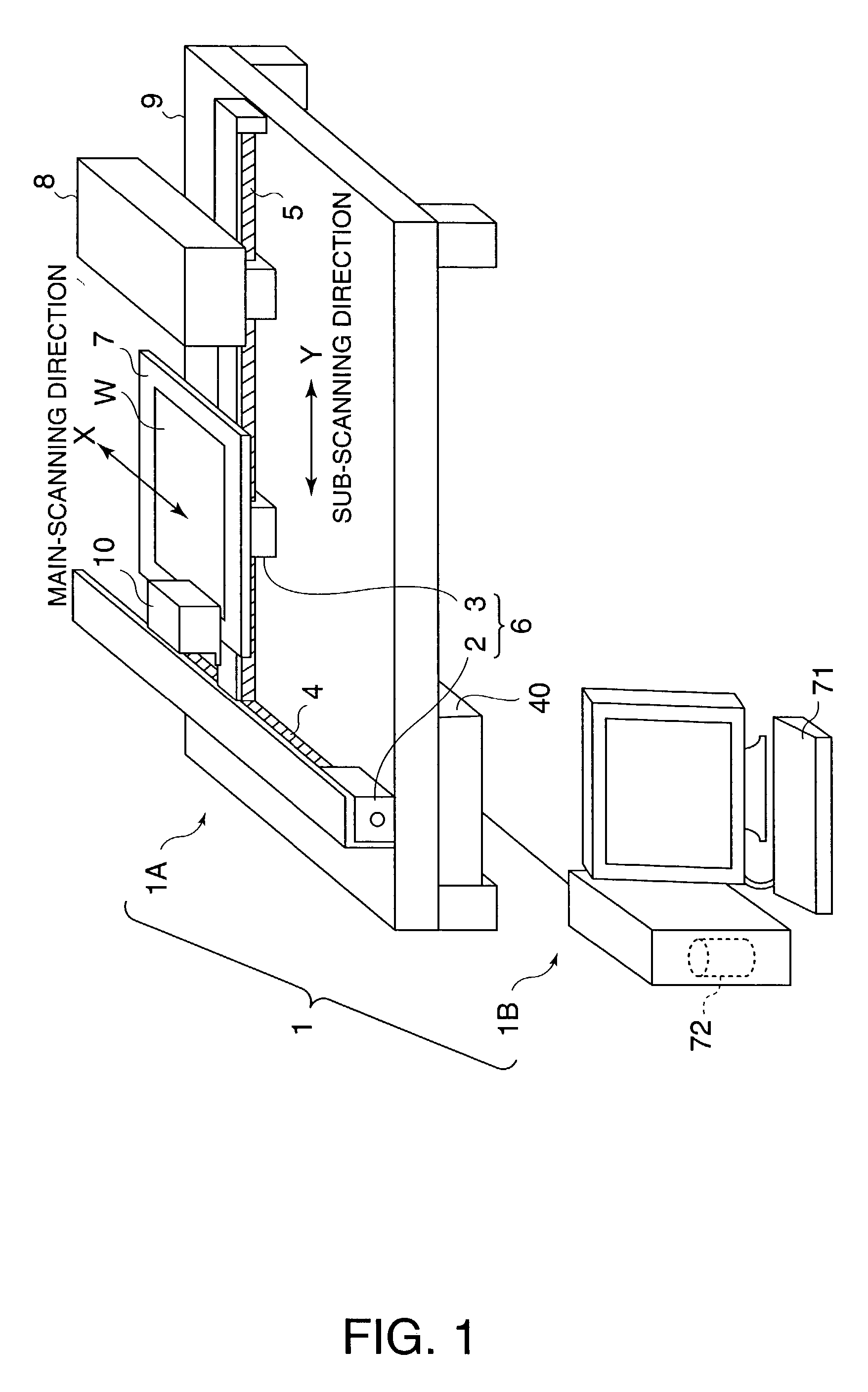
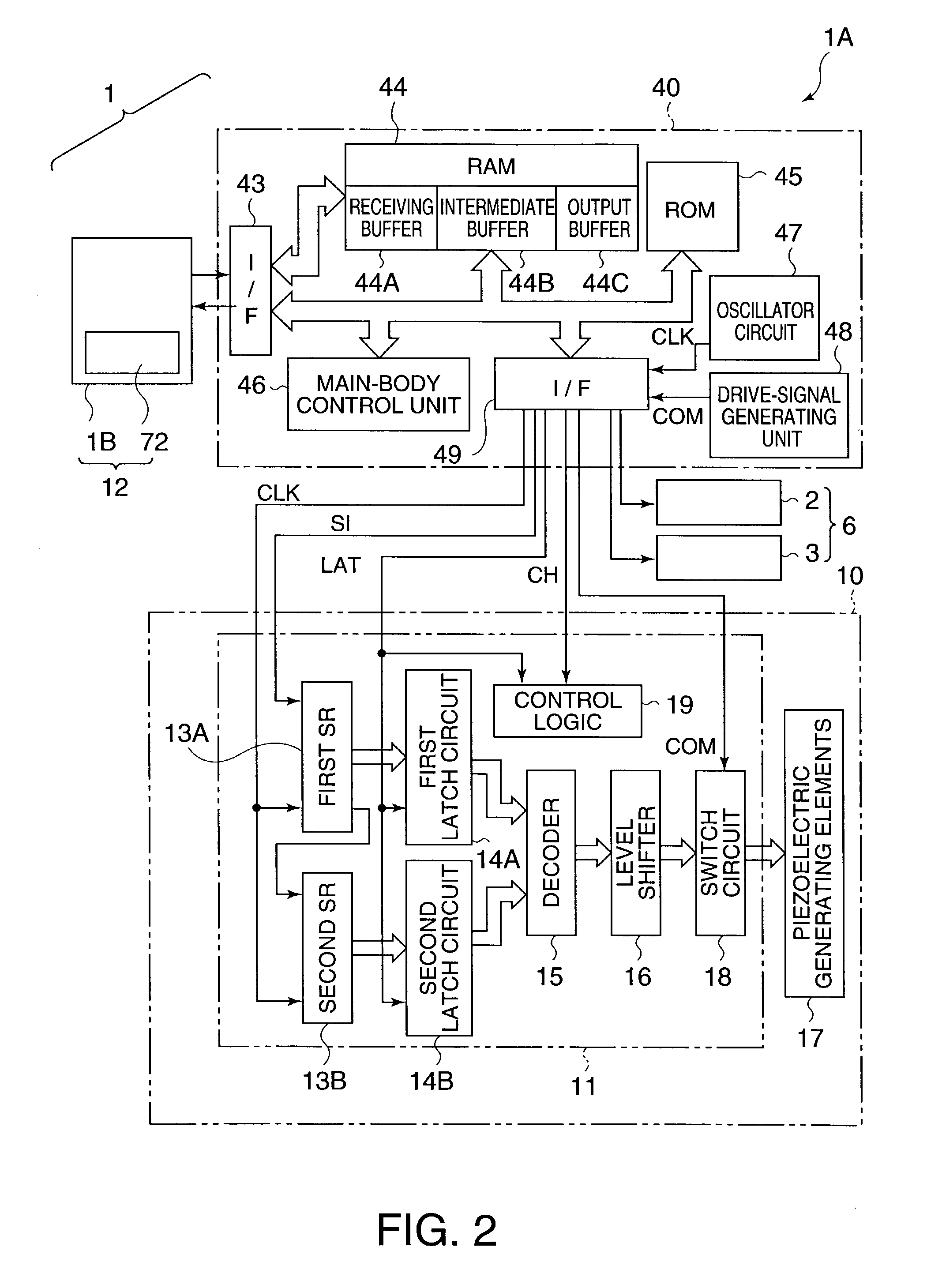
[0051]FIG. 1 is a schematic perspective view showing the overall construction of a discharge device according to a first embodiment of the present invention, and FIG. 2 is a functional block diagram of the discharge device shown in FIG. 1. As shown in FIG. 1, a discharge device 1 according to the present embodiment includes a main body 1A which is, for example, an inkjet discharge device, and a computer 1B.

[0052]The main body 1A includes a head 10, an X-direction drive shaft 4, an X-direction drive motor 2, a Y-direction guide shaft 5, a Y-direction drive motor 3, a control device 40, a stage 7, a cleaning mechanism 8, and a base 9. The computer 1B includes a keyboard 71 with which discharge conditions such as positions on a target W at which viscous liquid is to be discharged in the main body 1A can be input, and a storag...


PUM

PropertyMeasurementUnit
voltages VHaaaaaaaaaa
discharge weight Iwaaaaaaaaaa

Abstract

The invention provides a discharge device which forms microlenses, etc., with high precision. A switch circuit selects a predetermined one of drive pulses included in a drive signal on the basis of waveform selection data obtained from a control device, and applies the selected drive pulse.

Description

TECHNICAL FIELD[0001]The present invention relates to a discharge device which discharges viscous liquid such as resin, a method for controlling the discharge device, a discharge method using the discharge device, and methods for forming a microlens array, a color filter substrate, and an electrooptic device using the discharge method.BACKGROUND ART[0002]In liquid crystal displays, microlens arrays are used for efficiently utilizing incident light in a pixel area. Such microlens arrays are generally manufactured by applying a photosensitive resin on a transparent substrate by spin coating and forming a pattern by using photolithography techniques. However, if, for example, microlenses are formed by discharging a transparent resin (viscous liquid) in a matrix pattern by using a discharge method used in inkjet printers, inkjet plotters, etc., and curing the transparent resin, the efficiency in producing the microlens arrays is largely increased.[0003]Microlens arrays are also used in ...

Claims


Application Information

Patent Timeline
Patent Type & Authority Patents(United States)
IPC IPC(8): B05B17/04B05C5/00G02B5/20B05C11/10B05D3/00B05D5/06B41J2/045G02B3/00G02F1/13H01L51/50H05B33/10
CPCB41J2/04528B41J2/04581B41J2/04588B41J2/0459G02B3/0056B41J2/04596G02B3/0012G02B3/0043B41J2/04593B41J2202/09G02F1/13
Inventor USUDA, HIDENORI
Owner SEIKO EPSON CORP
Why Eureka
Try Eureka