Light guide plate, light source device equipped therewith and display device

a technology of light source device and light guide plate, which is applied in the direction of lighting and heating apparatus, instruments, machines/engines, etc., can solve the problems of low efficiency, low brightness, low efficiency, etc., and achieves high contrast, good display quality, and suppresses brightness dispersion

Inactive Publication Date: 2006-07-11
SHARP KK
View PDF7 Cites 153 Cited by
  • Summary
  • Abstract
  • Description
  • Claims
  • Application Information

AI Technical Summary

Benefits of technology

[0018]It is therefore an object of the present invention to provide a display device which suppresses dispersion in the brightness, features a high contrast and a good display quality, a power source device used therefor, and a light guide plate.

Problems solved by technology

The reflection type liquid crystal display device realizes a low power consumption accompanied, however, by such a problem that a good display quality is not obtained unless the display device is used in a sufficiently bright environment such as outdoors.
(1) Low Efficiency and Low Brightness.
Therefore, the utilization efficiency of light inevitably decreases.
In particular, when the point source of light is turned into a linear source of light by using a linear light guide plate 106, there exists a trade-off relationship between the light utilization efficiency and the uniformity in the distribution of light quantity, making it difficult to improve the light utilization efficiency.
Besides, it is necessary to precisely arrange the linear light guide plate 106, planar light guide plate 104 and LEDs 108, resulting in an increase in the cost of production.
Even by using the light guide plate 120 of the above structure in which light travels reciprocally, however, there remain problems as described below.
Besides, the light utilization efficiency inevitably drops due to the scattering of light or due to loss caused by scattering, and a complete solution is not obtained.
Moreover, the conventional front-light liquid crystal display device has a problem in that the contrast ratio of when the front-light is turned on is very smaller than the contrast ratio of when the back-light of the back-light liquid crystal display device is turned on.

Method used


Image

  • Light guide plate, light source device equipped therewith and display device
  • Light guide plate, light source device equipped therewith and display device
  • Light guide plate, light source device equipped therewith and display device

Examples


first embodiment

[0044]A light guide plate, a light source device equipped therewith and a display device according to a first embodiment of the invention will now be concretely described by way of Examples 1-1 to 1-6.

example 1-1

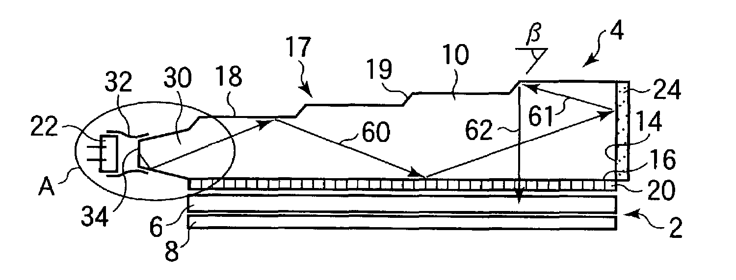
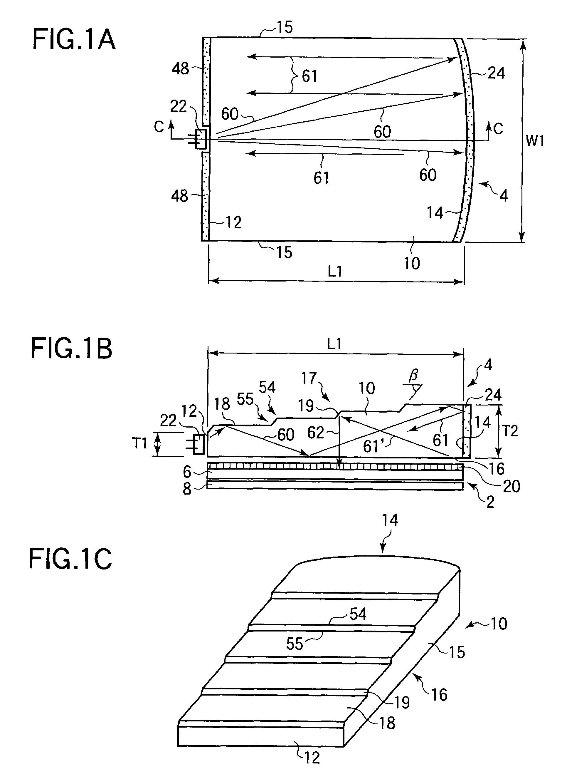
[0045]First, the light guide plate, light source device equipped therewith and display device according to Example 1-1 of the embodiment will be described with reference to FIGS. 1A to 1C. FIGS. 1A to 1C illustrate the constitutions of the light guide plate, light source device equipped therewith and display device according to the Example. FIG. 1A is a view illustrating the constitution of when the display device is viewed from the side of the display screen, FIG. 1B is a sectional view of the display device cut along the line C—C in FIG. 1A, and FIG. 1C is a perspective view illustrating the constitution of the light guide plate according to the Example. Referring to FIGS. 1A to 1C, the display device according to the Example includes a reflection type liquid crystal display panel 2 constituted by two pieces of substrates 6, 8 and liquid crystals (not shown) sealed between the two substrates 6, 8, and a light source device (front-light unit) 4 arranged near the substrate 6 on the ...

example 1-2

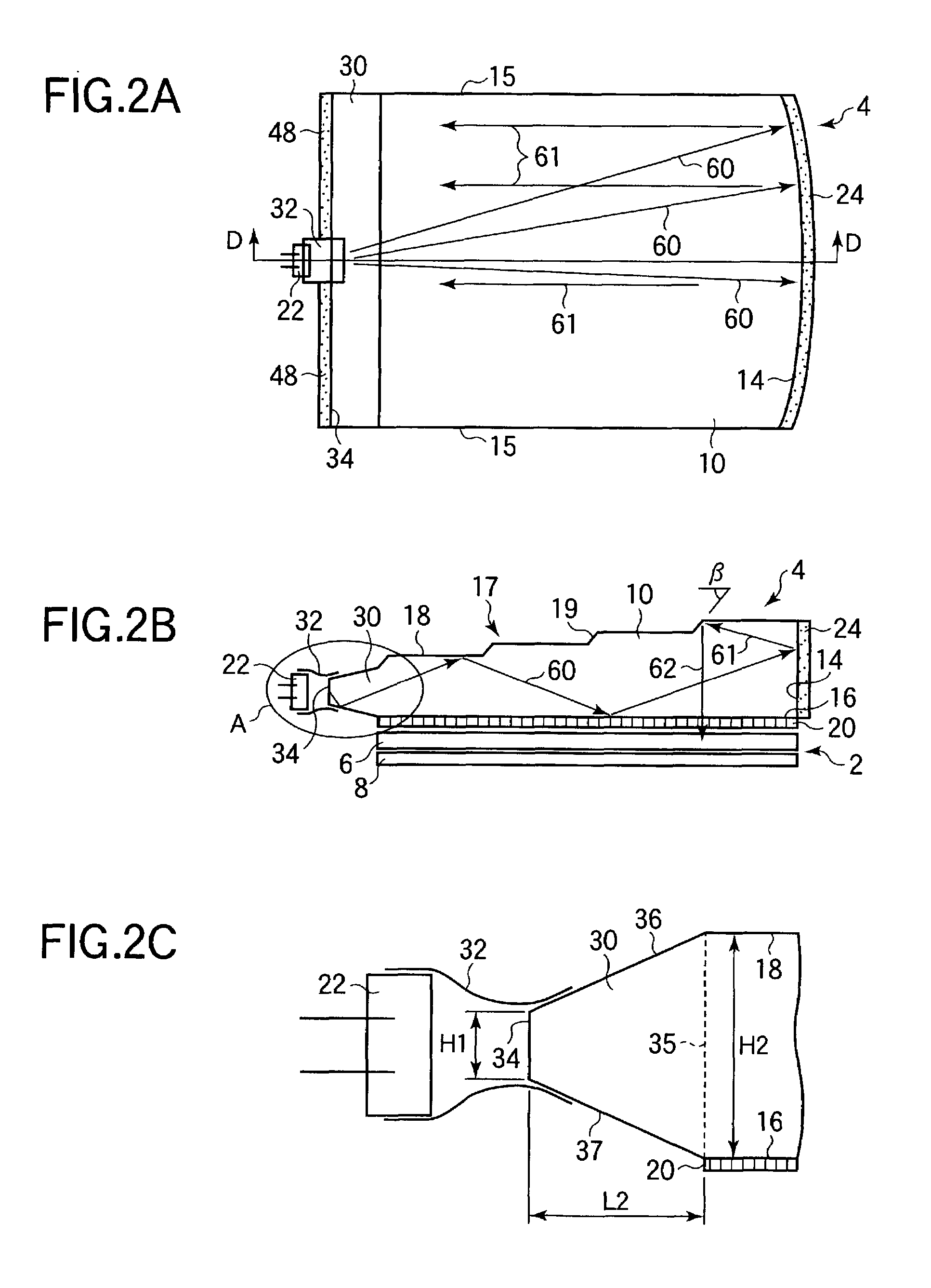
[0060]Next, the light guide plate, light source device equipped therewith and display device according to Example 1-2 of the embodiment will be described with reference to FIGS. 2A to 3. FIGS. 2A to 2C illustrate the constitutions of the light guide plate, light source device equipped therewith and display device according to the Example. FIG. 2A is a view illustrating the constitution of when the display device is viewed from the side of the display screen, FIG. 2B is a sectional view of the display device cut along the line D—D in FIG. 2A, and FIG. 2C is a view illustrating a region A of FIG. 2B on an enlarged scale. Constituent elements having the same functions and actions as those of the constituent elements of the light guide plate, light source device equipped therewith and display device of Example 1-1, are denoted by the same reference numerals but their description is not repeated. In the constitution of this Example, the first opposing surfaces 18 are in parallel with the...


PUM

PropertyMeasurementUnit
angleaaaaaaaaaa
angleaaaaaaaaaa
angleaaaaaaaaaa

Abstract

A display device used for a display unit of portable electronic equipment, a light source device therefor and a light guide plate, suppressing dispersion in the brightness and featuring a high contrast and a good display quality. The constitution includes a light incidence surface on where light emitted from an LED falls, a light reflection surface formed facing the light incidence surface and reflects light from the light incidence surface, a light outgoing surface arranged between the light incidence surface and the light reflection surface, and has a circularly polarizing plate intimately adhered onto the surface thereof, and an opposing surface formed facing the light outgoing surface and in which there are alternately arranged first opposing surfaces for guiding the incident light to the light outgoing surface as well as to the light reflection surface, and second opposing surfaces for emitting the light reflected by the light reflection surface through the light outgoing surface.

Description

BACKGROUND OF THE INVENTION[0001]1. Field of the Invention[0002]This invention relates to a display device used for a display unit such as of a portable electronic equipment, a light source device used therefor, and a light guide plate.[0003]2. Description of the Related Art[0004]Accompanying the widespread use of portable data terminals, it has been urged to provide a display device which consumes small amount of electric power. The reflection type liquid crystal display device realizes a low power consumption accompanied, however, by such a problem that a good display quality is not obtained unless the display device is used in a sufficiently bright environment such as outdoors. Therefore, the reflection type liquid crystal display device is generally used in combination with a front-light unit which is arranged on the side of the display screen and is illuminated with a plane source of light.[0005]As a source of light for the front-light unit, there is used a cold cathode tube or...

Claims


Application Information

Patent Timeline
Patent Type & Authority Patents(United States)
IPC IPC(8): F21V7/04G02B6/00F21V8/00F21Y101/02G02F1/13357
CPCG02B6/0016G02B6/0068G02B6/0048G02F1/1335
Inventor GOTOH, TAKESHIHAMADA, TETSUYASUZUKI, TOSHIHIROKOBAYASHI, TETSUYAHAYASHI, KEIJISUGAWARA, MARI
Owner SHARP KK
Why Eureka
Try Eureka