Accumulation, control and accounting of fluid by-product from a solid deposition modeling process

a solid deposition modeling and by-product technology, applied in the field of accumulation, control and accounting of fluid by-products from solid deposition modeling processes, can solve the problems of shortening the time to develop prototype parts, requiring different solutions to different problems, and quickly producing limited numbers of parts in rapid manufacturing processes. achieve the effect of reliable and precis

Active Publication Date: 2006-07-11
3D SYST INC
View PDF14 Cites 26 Cited by
  • Summary
  • Abstract
  • Description
  • Claims
  • Application Information

AI Technical Summary

Benefits of technology

[0013]The instant invention provides its benefits across any SFF process that requires removal of excess build and / or support material during a build. This is done by providing a reliable and precise system for accumulating, accounting for, and removing by-product waste material from a SFF device for forming three-dimensional objects.
[0016]It is another aspect of the instant invention to provide an improved by-product waste removal system that allows intervention in removing collected waste during the SFF build process without interrupting the build.
[0017]It is still another aspect of the instant invention to provide an improved by-product waste removal system that can accurately account for by-product waste removed.
[0019]It is an advantage that the by-product waste removal system of the present invention is lower in cost, simpler and more effective than prior by-product waste removal systems.

Problems solved by technology

For instance, SFF technologies dramatically shorten the time to develop prototype parts and can quickly produce limited numbers of parts in rapid manufacturing processes.
This is generally because there are substantial differences between the two processes, thus requiring different solutions to different problems.
The differences mentioned above are significant and create a number of problems to be resolved.
For instance, the amount of material deposited in ink jet based SDM techniques, both in volume and in mass, can be so substantial that it is generally considered impractical to mount a reservoir directly on the ink jet print head to hold all of the material.
In addition, a significant amount of energy is required to maintain the large quantity of material in the flowable state in the reservoir and in the delivery system during the build process.
This generates a significant amount of heat in the build environment.
Another problem that is unique to SDM techniques is that the layers being formed must be shaped or smoothed during the build process to establish a uniform layer thickness.
However, the planarizer produces waste material during the build process that must be handled.
For example, most photopolymers are reactive, and excessive contact to human skin may result in sensitivity reactions.
However, SDM operators who normally handle even non-reactive materials consider additional handling procedures inconvenient and, if possible, would prefer they be eliminated.
A lack of sufficient buffering capacity can result in too much by-product waste material backing up in the system.

Method used


Image

  • Accumulation, control and accounting of fluid by-product from a solid deposition modeling process
  • Accumulation, control and accounting of fluid by-product from a solid deposition modeling process
  • Accumulation, control and accounting of fluid by-product from a solid deposition modeling process

Examples


Embodiment Construction

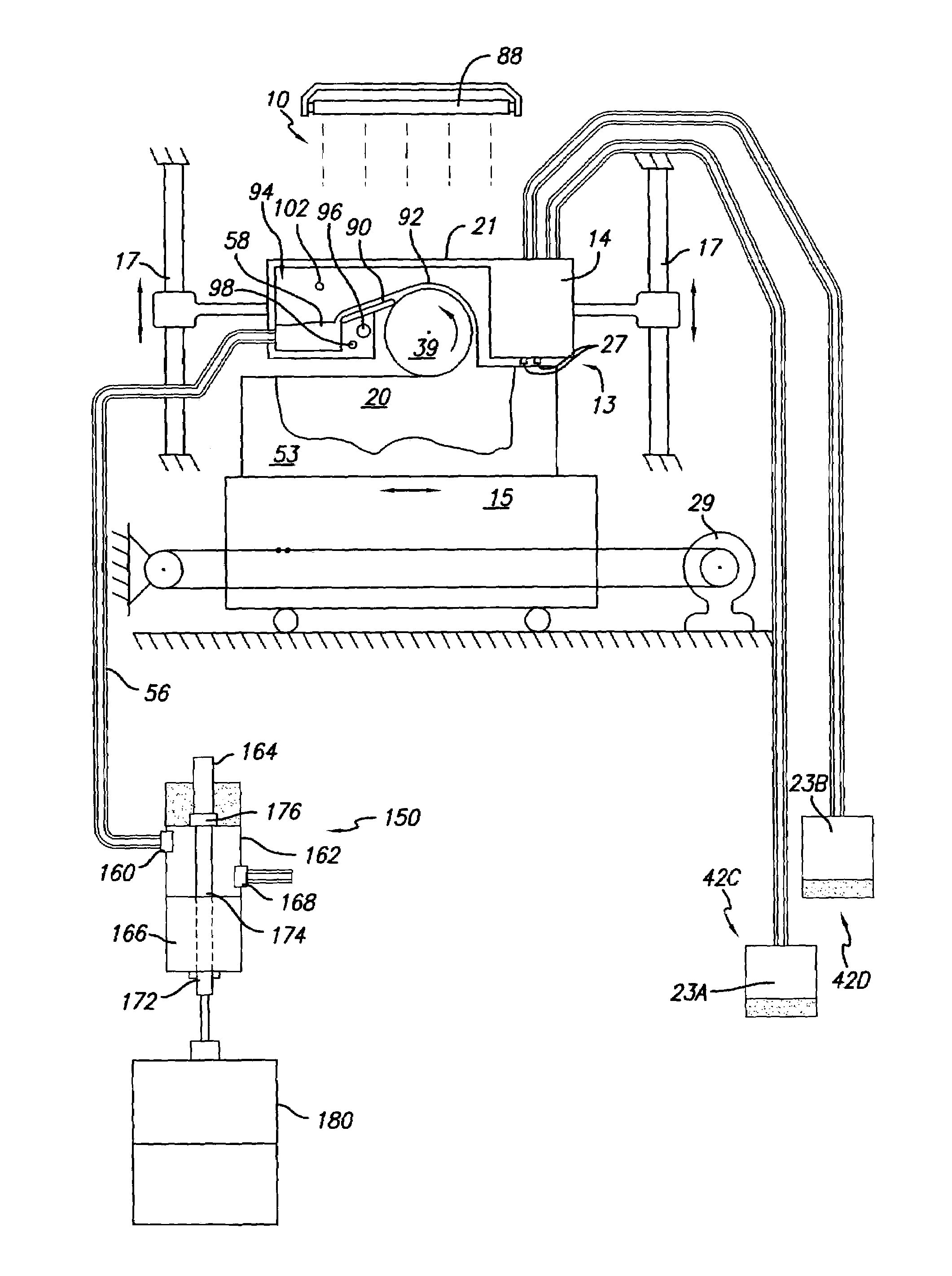
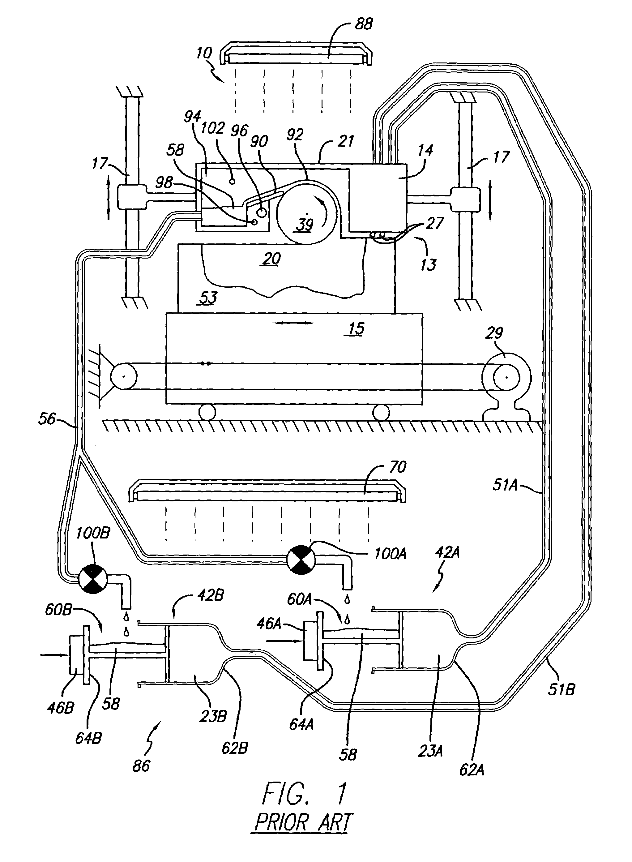
[0029]The present invention provides its benefits across a broad spectrum of SFF processes. While the description which follows hereinafter is meant to be representative of a number of such applications, it is not exhaustive. As will be understood, the basic apparatus and methods taught herein can be readily adapted to many uses. It is intended that this specification and the claims appended hereto be accorded a breadth in keeping with the scope and spirit of the invention being disclosed despite what might appear to be limiting language imposed by the requirements of referring to the specific examples disclosed.

[0030]While the present invention can be applicable to other SFF techniques and objects made therefrom, the invention will be described with respect to solid deposition modeling (SDM) utilizing a build material dispensed in a flowable state. However it is to be appreciated that the present invention can be implemented with any SFF technique that requires the continuous or in...


PUM

PropertyMeasurementUnit
thermal energyaaaaaaaaaa
pressureaaaaaaaaaa
mechanical propertiesaaaaaaaaaa

Abstract

A by-product waste material removal system for solid deposition modeling. As excess build and support material is removed during the build as a by-product waste the removal system accumulates, measures, and releases the by-product waste material into a waste receptacle for disposal. The by-product waste material removal system requires no mechanical vacuum systems and allows operator intervention to remove and replace waste receptacles without interrupting an ongoing build.

Description

BACKGROUND OF THE INVENTION[0001]1. Field of the Invention[0002]The invention relates in general to a system and a method for accurately metering, accumulating, and accounting for the by-product waste stream generated from a solid deposition modeling process. In addition, the system allows operator intervention during the fabrication process and can be integrated with a sealed waste removal system wherein reactive materials can be employed without special handling procedures.[0003]2. Description of the Prior Art[0004]Recently, several new technologies have been developed for the rapid creation of models, prototypes, and parts for limited run manufacturing. These new technologies can generally be described as solid freeform fabrication, herein referred to as “SFF”. Some SFF techniques include stereolithography, selective deposition modeling, laminated object manufacturing, selective phase area deposition, multi-phase jet solidification, ballistic particle manufacturing, fused deposit...

Claims


Application Information

Patent Timeline
Patent Type & Authority Patents(United States)
IPC IPC(8): B28B17/00B29B17/00B29C35/08B29C41/02B29C41/36B29C41/52B29C67/00
CPCB29B17/0005B29C67/0096B29C41/52B29C41/36Y02W30/62B29C64/35B33Y30/00B33Y40/00B33Y40/20
Inventor STOCKWELL, JOHN S.BISHOP, RAYMOND J.SOLIZ, RAYMOND MATHEWFONG, JON JODY
Owner 3D SYST INC
Why Eureka
Try Eureka