Multiphase mixing device with improved quench injection for inducing rotational flow

a multi-phase mixing and rotational flow technology, applied in chemical/physical/physical-chemical processes, chemical apparatus and processes, physical/chemical process catalysts, etc., can solve the problems of poor performance, increased inlet temperature differences following the quench zone, and failure of the quench zone to erase the lateral temperature differences at the outlet of the preceding bed, etc., to achieve significant improvement in the mixing of quench fluid and improve the effect of quench injection

Inactive Publication Date: 2006-07-11
EXXON RES & ENG CO
View PDF20 Cites 12 Cited by
  • Summary
  • Abstract
  • Description
  • Claims
  • Application Information

AI Technical Summary

Benefits of technology

[0022]In addition, the teachings described in applicant's co-pending application entitled “MULTIPHASE MIXING DEVICE WITH IMPROVED QUENCH INJECTION” may generally be combined with the teachings herein. As a result of injecting quench at the specific locations and in the specific directions dictated by the teachings of the co-pending application, significant improvements in mixing efficiency are obtained. Those teachings may be combined with the teachings designed to induce rotational flow contained herein. In particular, a combination of the teachings allows for mixing of quench fluid to be significantly improved when quench is introduced into a region above the collection tray and where (i) lateral velocities of the process fluids are low, (ii) sufficient volume is available for the quench fluid to mix with the process fluids, and (iii) quench injection occurs so as to induce a rotational flow in the horizontal plane with a significant angular velocity component.

Problems solved by technology

First, the quench zone fails to erase lateral temperature differences at the outlet of the preceding bed or, in the worst cases, amplifies them.
The second sign of poor performance is that inlet temperature differences following the quench zone increase as the rate of quench gas is raised.
This indicates inadequate mixing of cooler gas with the hot process fluids.
Poor quench zone performance limits reactor operation in various ways.
When interbed mixing is unable to erase temperature differences, these persist or grow as the process fluids move down the reactor.
Hot spots in any bed lead to rapid deactivation of the catalyst in that region which shortens the total reactor cycle length.
Product selectivities are typically poorer at higher temperatures; hot regions can cause color, viscosity and other qualities to be off-specification.
), the exothermic reactions may become self-accelerating leading to a runaway which can damage the catalyst, the vessel, or downstream equipment.
Cognizant of these hazards, refiners operating with poor internal hardware must sacrifice yield or throughput to avoid these temperature limitations.
While the above mentioned systems may provide significant improvements in process fluid mixing efficiency, they do suffer from less than ideal quench mixing efficiency.
In this design, it is also believed that the quench location may be located too closely to the wall of the vessel, leaving inadequate mixing volume between the injection point and the wall.
However, the efficiency of this device is sensitive to the degree of phase segregation achieved at the interbed inlet and thus may not perform as desired under all conditions and with respect to particular reactant characteristics.
The above and other known mixing systems generally suffer from the fact that there is insufficient space within the mixing chamber to promote intense two-phase mixing.
This limits the capability of these systems to homogenize quench fluid with process fluids and to erase temperature differences between fluids from different sections of the reactor.
While the disclosed process and apparatus represent a significant improvement in the art, the system described in the co-pending application does not employ quench injection with a rotational component and does not, therefore benefit from the results attained therewith.

Method used


Image

  • Multiphase mixing device with improved quench injection for inducing rotational flow
  • Multiphase mixing device with improved quench injection for inducing rotational flow
  • Multiphase mixing device with improved quench injection for inducing rotational flow

Examples


Embodiment Construction

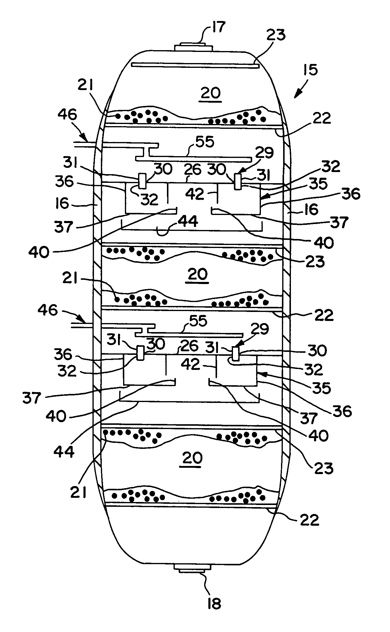
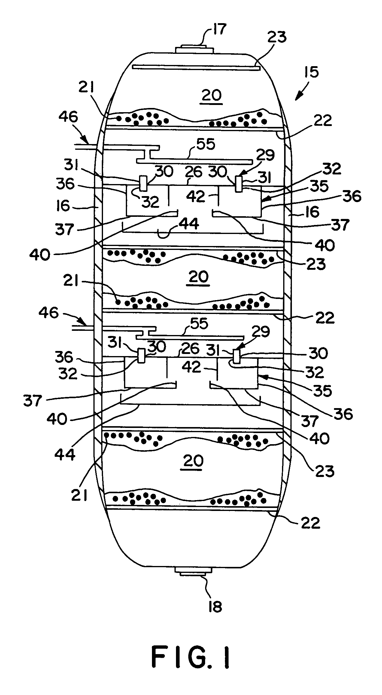
[0027]FIG. 1 shows, in simplified form, a hydroprocessing reactor column in accordance with the present invention. The general configuration of the reactor is conventional, as are details such as the supports for the grids and distributor plates which are not shown for purposes of clarity. The reactor column 15 is formed as a generally cylindrical chamber having an outer wall 16. A reactor inlet 17 and a reactor outlet 18 are provided for introducing and discharging fluids from the reactor column 15. The reactor column 15 further comprises one or more catalyst beds 20 positioned along the longitudinal axis of the reactor column 15. Each of the catalyst beds 20 contains catalyst material 21 which is preferably supported below by a catalyst support grid 22. The catalyst support grid 22, together with the outer wall 16, provides direct support for the catalyst material 21. Alternatively, the catalyst support grid 22 may provide indirect support for the catalyst 21 by retaining one or m...


PUM

PropertyMeasurementUnit
angleaaaaaaaaaa
anglesaaaaaaaaaa
angleaaaaaaaaaa

Abstract

A mixing system is disclosed which provides improved multiphase mixing through the use of a novel quench injection means. The mixing system comprises a horizontal collection tray, a mixing chamber positioned below the collection tray, and at least one passageway extending through the collection tray into the mixing chamber. The mixing chamber and the collection tray define a two-phase mixing volume. The passageway conducts fluid from above the collection tray into the mixing chamber. The mixing chamber preferably includes at least one outlet opening for the downward passage of fluid. In particular, mixing of quench fluid is significantly improved when quench is introduced into a region above the collection tray and where a preferred direction of quench injection is selected to cause a rotational current on the collection tray.

Description

FIELD OF THE INVENTION[0001]The present invention relates generally to systems for mixing process gases and liquids and more specifically to interbed quench and mixing systems involving cocurrent and countercurrent downflow reactors using fixed hardware.BACKGROUND OF THE INVENTION[0002]Downward flow reactors are used by the chemical and refining industries in a variety of processes, such as hydrotreating, hydrofinishing and hydrocracking. A typical downward flow reactor has a cylindrical outer wall with a catalyst bed positioned within the reactor. The catalyst bed generally rests on a catalyst support grid positioned horizontally within the reactor and spanning the complete diameter of the reactor. The catalyst support grid, together with the outer wall, cooperate to retain the catalyst or other particulate material in place. A distribution tray is positioned horizontally within the reactor at a location above the catalyst bed for evenly distributing process fluids onto the catalys...

Claims


Application Information

Patent Timeline
Patent Type & Authority Patents(United States)
IPC IPC(8): B01J8/04B01J35/02B01F3/04B01F5/04B01J8/00B05B1/20C10G49/00
CPCB01J8/0453B01J8/0492C10G49/002B05B1/207B01J2208/00849
Inventor MULDOWNEY, GREGORY P.CHUBA, MICHAEL R.
Owner EXXON RES & ENG CO
Why Eureka
Try Eureka