Molehole embedded 3-D crossbar architecture used in electrochemical molecular memory device

a molecular memory and molecular structure technology, applied in the field of molecular electronics and microelectronics, can solve the problems of not being able to prepare sub-micron structures, not being able to provide a convenient method of regulating the relative surface area of the electrodes exposed in the vial, and not being able to achieve large precisely arranged arrays of such vials, so as to achieve suitable mechanical properties and prevent charge leakage

Inactive Publication Date: 2006-07-11
RGT UNIV OF CALIFORNIA
View PDF23 Cites 44 Cited by
  • Summary
  • Abstract
  • Description
  • Claims
  • Application Information

AI Technical Summary

Benefits of technology

[0032]The term “storage medium” refers to a composition comprising two or more storage molecules. The storage medium can contain only one species of storage molecule or it can contain two or more different species of storage molecule. In preferred embodiments, the term “storage medium” refers to a collection of storage molecules. Preferred storage media comprise a multiplicity (at least 2) of different and distinguishable (preferably non-neutral) oxidation states. The multiplicity of different and distinguishable oxidation states can be produced by the combination of different species of storage molecules, each species contributing to said multiplicity of different oxidation states and each species having a single non-neutral oxidation state. Alternatively or in addition, the storage medium can comprise one or more species of storage molecule having a multiplicity of non-neutral oxidation states. The storage medium can contain predominantly one species of storage molecule or it can contain a number of different storage molecules. The storage media can also include molecules other than storage molecules (e.g. to provide chemical stability, suitable mechanical properties, to prevent charge leakage, etc.).

Problems solved by technology

Previous approaches, however, have not provided a convenient method of regulating the relative surface area of the electrodes exposed in the vials, have not been convenient for the fabrication of large precisely arranged arrays of such vials, or have not been feasible for the preparation of sub micron structures.

Method used


Image

  • Molehole embedded 3-D crossbar architecture used in electrochemical molecular memory device
  • Molehole embedded 3-D crossbar architecture used in electrochemical molecular memory device
  • Molehole embedded 3-D crossbar architecture used in electrochemical molecular memory device

Examples


Embodiment Construction

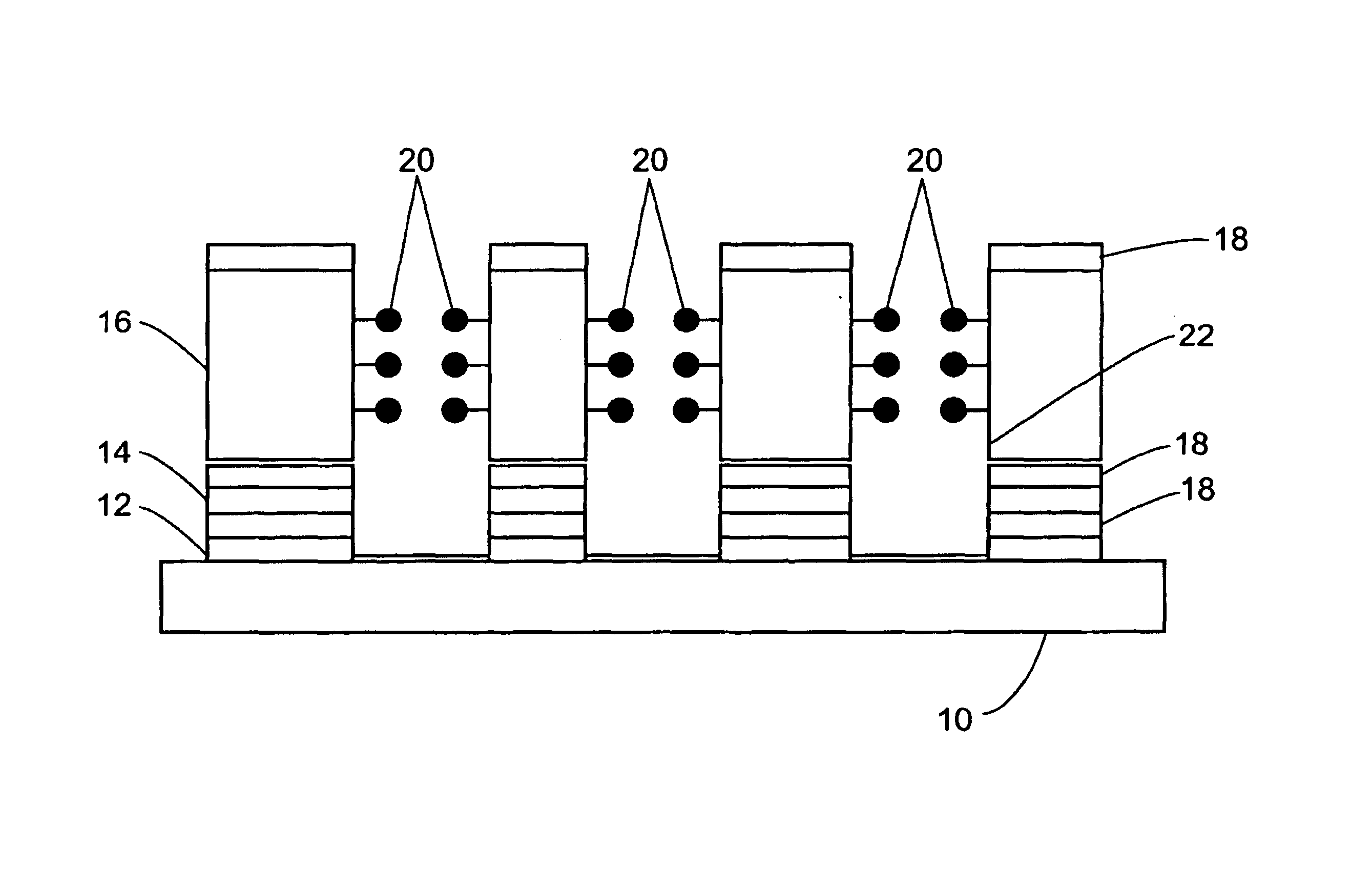
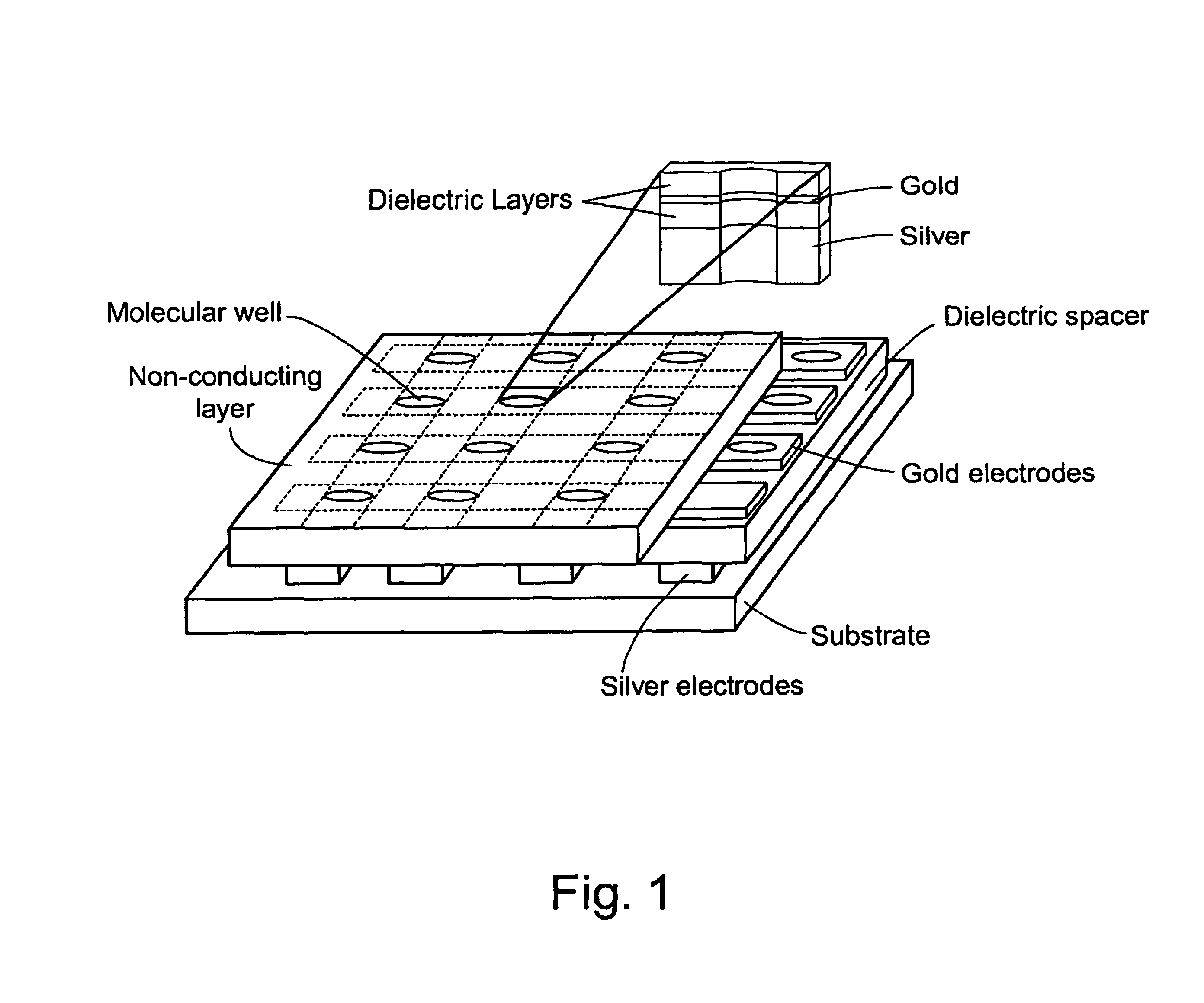
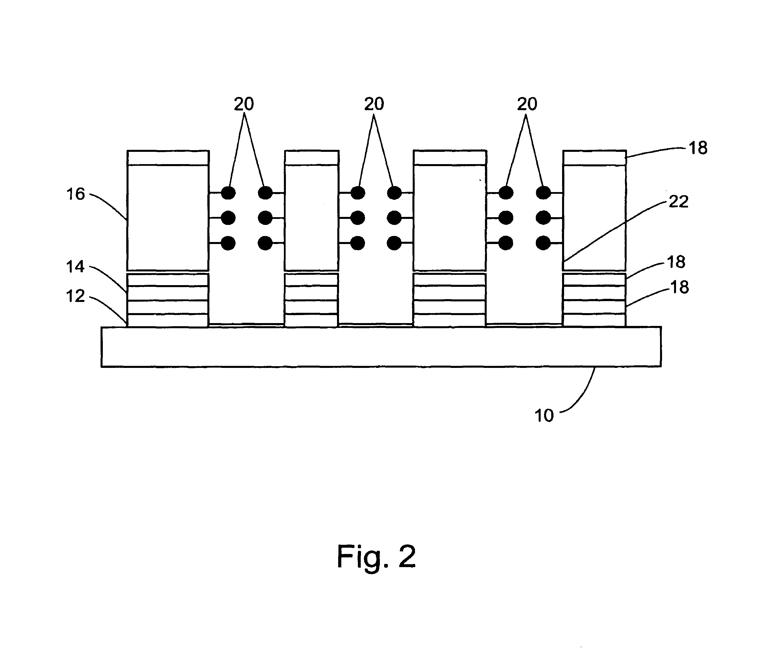
[0083]This invention pertains to the design and fabrication of a novel architecture that can be used for a molecular electrochemical memory device, a sensor, and a variety of other applications. The unique architecture is comprised, in certain embodiments, of two or more arrays of conductors (e.g. electrodes) arranged so that the conductors forming the cross or overlap each other. The conductors are typically separated by a dialectric layer. Within each intersection point of an upper and lower electrode (e.g. top and bottom interconnect) a well is fabricated. This well penetrates the electrodes, so that the electrodes form a portion of the side and / or bottom of the well.

[0084]Molecules (e.g. organic molecules) are attached to one ormore of the exposed conductor surfaces in the wells. Each well can then function as an electrochemical cell permitting electrochemical measurements of the bound molecules or of other molecules attached to the bound molecules.

[0085]The fabrication methods ...


PUM

PropertyMeasurementUnit
volumeaaaaaaaaaa
volumeaaaaaaaaaa
distanceaaaaaaaaaa

Abstract

This invention provides a new design and fabrication for a three-dimensional crossbar architecture embedding a sub-micron or nanometer sized hole (called a molehole) in each cross-region. Each molehole is an electrochemical cell consisting of two or more sectional surfaces separated by a non-conductor (e.g. a dialectric layer and solid electrolyte). When used in electrochemical molecular memory device (EMMD), the architecture provides unique features such as a nano-scale electroactive surface, no interaction between memory elements, and easier miniaturization and integration.

Description

STATEMENT AS TO RIGHTS TO INVENTIONS MADE UNDER FEDERALLY SPONSORED RESEARCH AND DEVELOPMENT[0001]This invention was made with Government support under Grant No: N00014-99-0357 awarded by the Office of Naval Research. The Government of the United States of America may have certain rights in this invention.CROSS-REFERENCE TO RELATED APPLICATIONS[0002][Not Applicable]FIELD OF THE INVENTION[0003]This invention pertains to the fields of microelectronics and molecular electronics. In particular this invention involves the design and fabrication of a novel architecture that can be used for a molecular electrochemical memory device or for a sensor array.BACKGROUND OF THE INVENTION[0004]There has been a great interest in the development of nanoliter to picoliter microvials in analytical chemistry. Arrays of vials containing nanoliter to picoliter volumes have been etched in silicon for sample introduction in capillary electrophoresis and mass spectroscopy (Clark and Ewing (1998) Anal. Chem....

Claims


Application Information

Patent Timeline
Patent Type & Authority Patents(United States)
IPC IPC(8): G11C11/00G11C13/00G01N33/483C12N15/09G01N27/403G01N27/416G01N33/543G01N37/00G11C11/56G11C13/02H01L27/28H01L51/05H01M4/38H01M4/60H01M6/40H01M10/04
CPCG11C11/5664G11C13/0009G11C13/0014G11C13/0016G01N27/3278H01M4/602H01M6/40H01M10/0436B82Y10/00G01N33/5438H01M4/38G11C2213/77Y02E60/10Y02P70/50H01L29/82
Inventor KUHR, WERNER G.BOCIAN, DAVID F.LIU, ZHIMINGYASSERI, AMIR
Owner RGT UNIV OF CALIFORNIA
Why Eureka
Try Eureka