Eureka AIR delivers breakthrough ideas for toughest innovation challenges, trusted by R&D personnel around the world.

Vane

a technology of gas turbine engine and vane, which is applied in the direction of machines/engines, stators, efficient propulsion technologies, etc., can solve the problems of dampening vane vibration and affecting engine fuel efficiency

Active Publication Date: 2021-03-18
ROLLS ROYCE PLC
View PDF0 Cites 3 Cited by
  • Summary
  • Abstract
  • Description
  • Claims
  • Application Information

AI Technical Summary

Benefits of technology

The patent describes a new type of vane for a gas turbine engine that is made from a three-dimensional weave of composite material. This allows for a lighter vane to be manufactured that has suitable mechanical properties for use in a structural application. The weave consists of warp fibers and weft fibers, with a ratio of warp to weft fibers greater than 50:50. The vane may also have a hollow core and a damping material to dampen vibration. Additionally, a metal or carbon fiber composite rod may be provided within the hollow core to improve stiffness. The technical effects of this invention include improved fuel efficiency and stiffness in the vane structure.

Problems solved by technology

These vanes are typically heavy, which impacts fuel efficiency of the engine.
The damping material may dampen vibration of the vane.
This is in contrast to stator vane rings which are configured to withstand aerodynamic loads, but are not configured to transfer significant structural loads.
In contrast, downstream stator vanes provided between successive rotor stages are generally configured to withstand aerodynamic loads, but are not configured to transfer significant structural loads across the core annulus.

Method used


Image

  • Vane
  • Vane
  • Vane

Examples


Embodiment Construction

[0071]Aspects and embodiments of the present disclosure will now be discussed with reference to the accompanying figures. Further aspects and embodiments will be apparent to those skilled in the art.

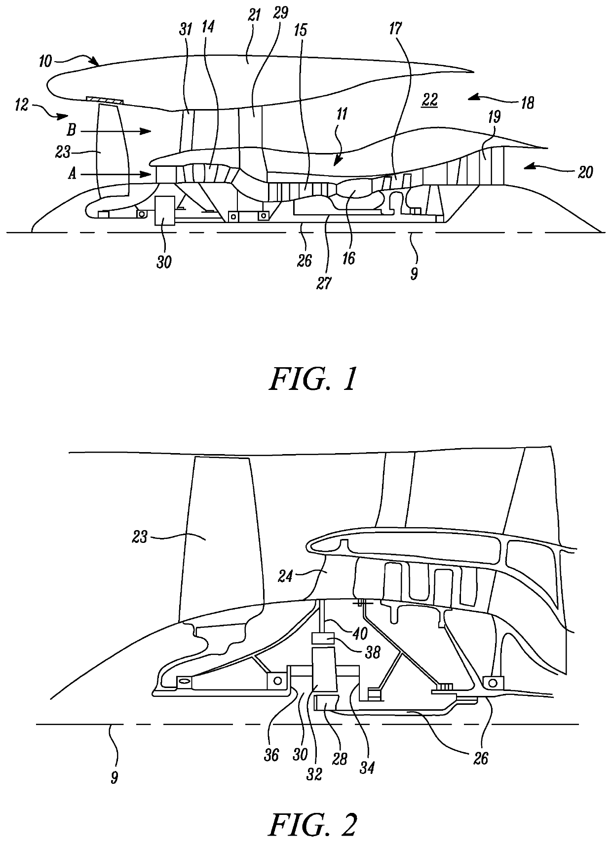
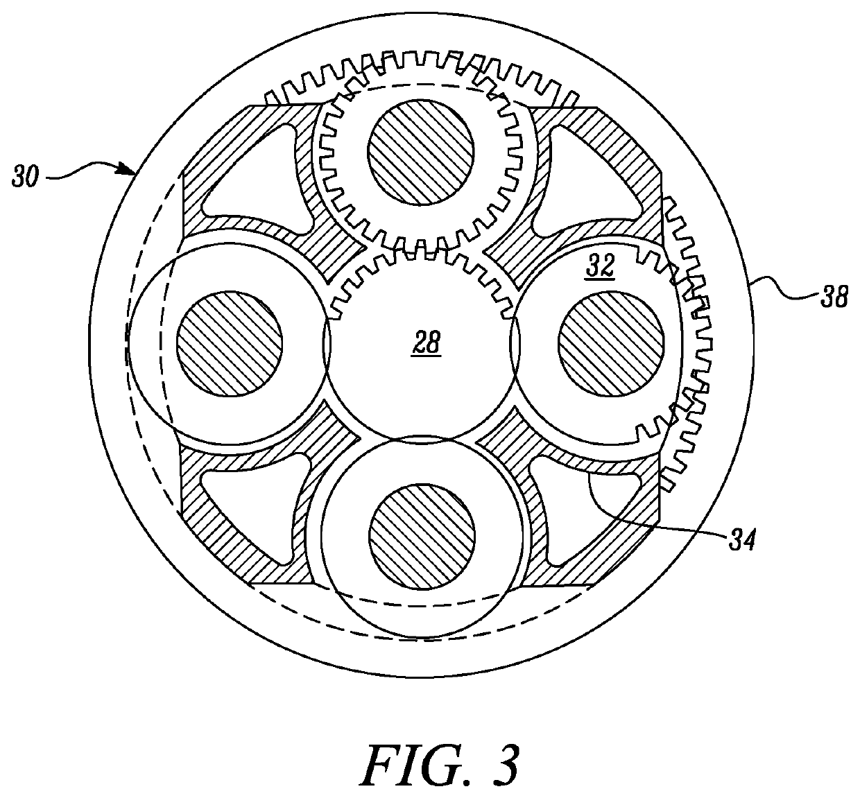
[0072]FIG. 1 illustrates a first example gas turbine engine 10 having a principal rotational axis 9. The engine 10 comprises an air intake 12 and a propulsive fan 23 that generates two airflows: a core airflow A and a bypass airflow B. The gas turbine engine 10 comprises a core 11 that receives the core airflow A. The engine core 11 comprises, in axial flow series, a low pressure compressor 14, a high-pressure compressor 15, combustion equipment 16, a high-pressure turbine 17, a low pressure turbine 19 and a core exhaust nozzle 20. A nacelle 21 surrounds the gas turbine engine 10 and defines a bypass duct 22 and a bypass exhaust nozzle 18. The bypass airflow B flows through the bypass duct 22. The fan 23 is attached to and driven by the low pressure turbine 19 via a shaft 26 and an epicy...


PUM


Abstract

There is disclosed a vane for a gas turbine engine, the vane comprising a three-dimensional weave of composite material. The vane is hollow to define a hollow core, wherein the vane has a maximum thickness (T), and a maximum wall thickness (WT) between an inner surface and an outer surface in a direction normal to the outer surface, wherein WT≤0.1T. Also disclosed is a method of manufacturing a composite vane for a gas turbine engine, the method comprising: forming a preform for the vane comprising a three-dimensional weave of composite material; and curing the preform. The preform has an internal hollow region, and the cured vane has a maximum thickness (T), and a maximum wall thickness (WT) between an inner surface and an outer surface in a direction normal to the outer surface, wherein WT≤0.1T.

Description

CROSS-REFERENCE TO RELATED APPLICATIONS[0001]This specification is based upon and claims the benefit of priority from UK Patent Application Number 1913394.1 filed on 17 Sep. 2019, the entire contents of which are incorporated herein by reference.BACKGROUNDTechnical Field[0002]The present disclosure relates to a vane for a gas turbine engine and a method of manufacturing a composite vane for a gas turbine engine.Description of the Related Art[0003]Structural vanes, such as those used in stator vane rings of gas turbine engines are typically metallic components. These vanes are typically heavy, which impacts fuel efficiency of the engine. It is therefore desirable to provide an improved arrangement.SUMMARY[0004]According to a first aspect there is provided a vane for a gas turbine engine, the vane comprising a three-dimensional weave of composite material, wherein the vane is hollow to define a hollow core, and wherein the vane has a maximum thickness T, and a maximum wall thickness W...

Claims


Application Information

Patent Timeline
Patent Type & Authority Applications(United States)
IPC IPC(8): F01D9/04F02C7/36F02C7/06F01D5/18
CPCF01D9/041F02C7/36F02C7/06F05D2300/603F05D2220/32F05D2240/12F05D2230/21F01D5/18F01D5/282F01D5/16F01D9/065F01D9/042F01D25/34F01D25/16F05D2260/96F05D2300/6034Y02T50/60
Inventor BACKHOUSE, ROBERT C.JONES, CHRISTOPHER D.
Owner ROLLS ROYCE PLC
Why Eureka
Eureka Blog
Learn More