Light source unit and projector
a technology of light source and projector, which is applied in the direction of point-like light sources, lighting and heating apparatus, instruments, etc., can solve the problems of difficulty in reducing the electromagnetic waves coming from light-emitting systems to a sufficient level, and achieve the effect of reducing the generation of unnecessary electromagnetic waves and reducing the emission of unnecessary electromagnetic waves
- Summary
- Abstract
- Description
- Claims
- Application Information
AI Technical Summary
Benefits of technology
Problems solved by technology
Method used
Image
Examples
first exemplary embodiment
[0026][First Exemplary Embodiment]
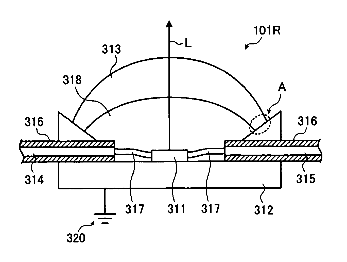
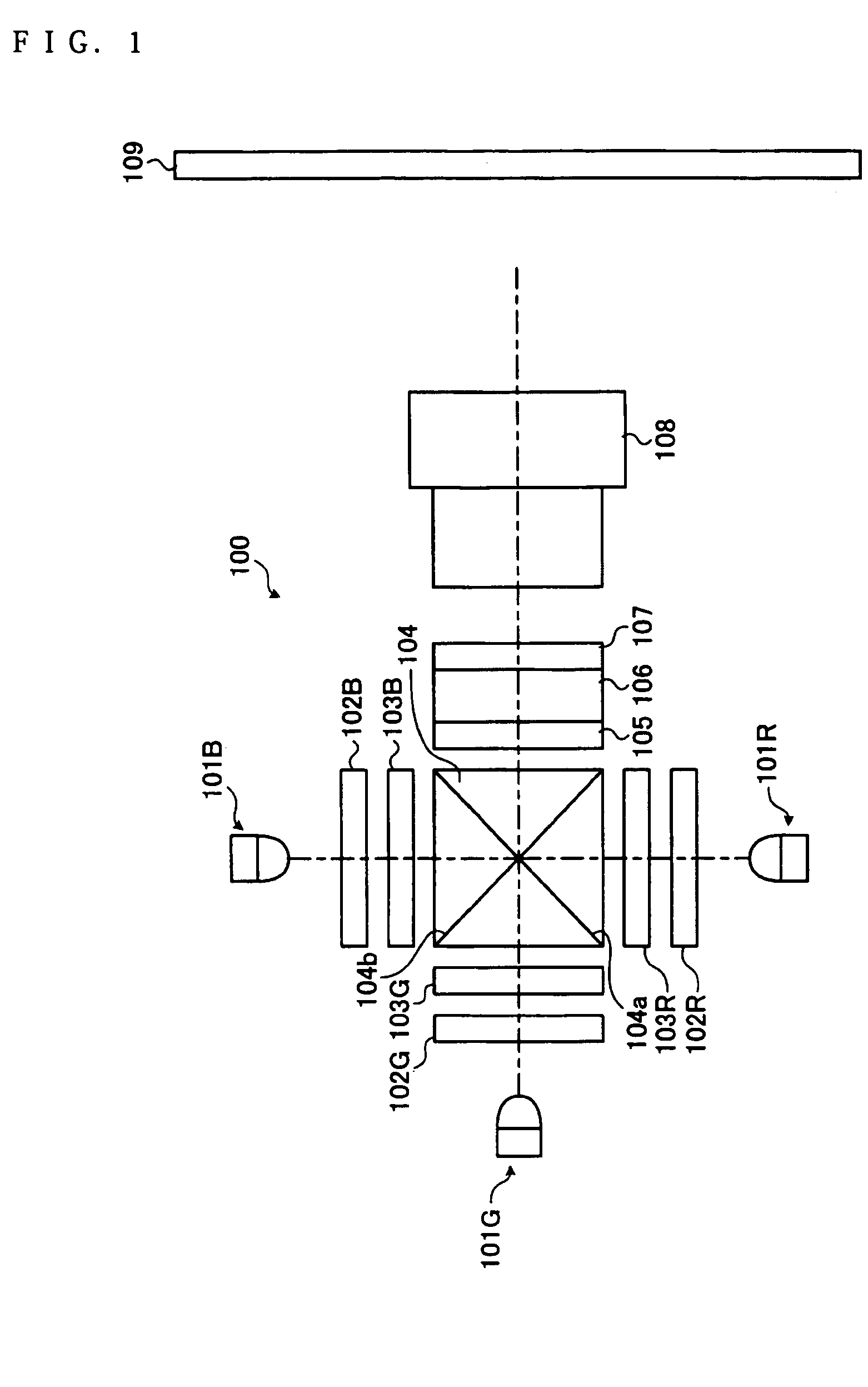
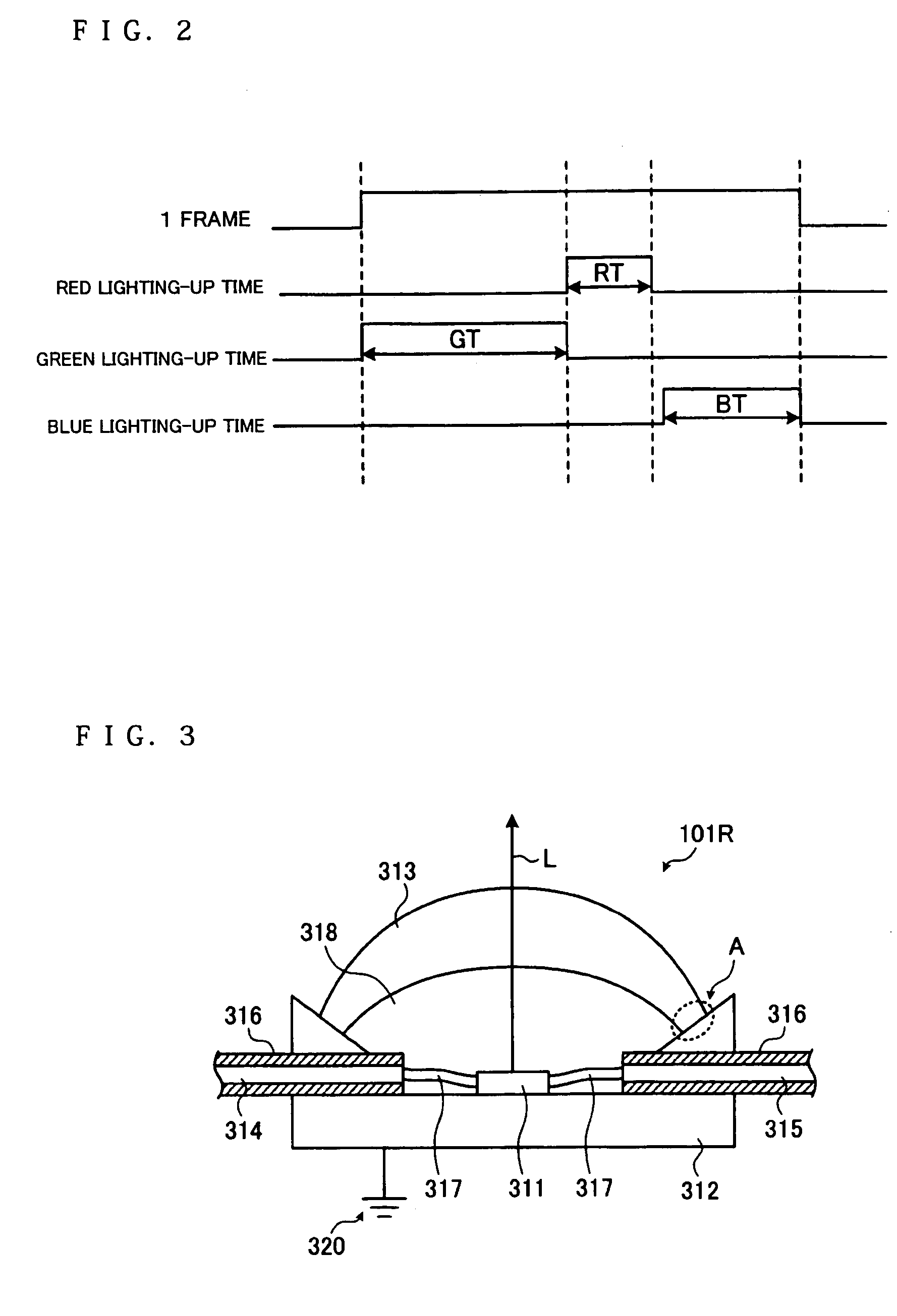
[0027]FIG. 1 is a schematic showing the structure of a projector 100 of a first exemplary embodiment of the present invention. In the present exemplary embodiment, described first is the schematic structure of the projector 100 in its entirety, and then the structure of a light source unit. The projector 100 includes a Red LED 101R that is a light source unit for Red light beams, a Green LED 101G that is a light source unit for Green light beams, and a Blue LED 101B that is a light source unit for Blue light beams.
[0028]The Red light beams from the Red LED 101R pass through λ / 4 phase plate 102R, and enter a reflective polarizing plate 103R. The reflective polarizing plate 103R passes through polarized light beams in a specific oscillation direction, e.g., p polarized light beams, and reflects polarized light beams in an oscillation direction different from the specific oscillation direction, e.g., s polarized light beams. The p polarized light beams...
second exemplary embodiment
[0059][Second Exemplary Embodiment]
[0060]FIG. 5 shows the cross-sectional structure of a Red LED 501R serving as a light source unit of a second exemplary embodiment of the present invention. The Red LED 501R can be applied to the projector 100 of the above first exemplary embodiment. Any part identical to the above first exemplary embodiment is provided with the same reference numeral, and is not described again if already described. The Red LED 501R of the present exemplary embodiment is provided such that a surface member 553 is provided to the light-emitting side of a cap section 513.
[0061]The cap section 513 is made from a transparent member, e.g., transparent resin, that is conventionally popular or popular in the related art for LEDs. The surface member 553 provided to the light-emitting side of the cap section 513 is made from an optically transparent conductive member. The surface member 553 includes, for example, a transparent conductive film formed by evaporating ITO, ZnO...
third exemplary embodiment
[0063][Third Exemplary Embodiment]
[0064]FIG. 6 shows the cross-sectional structure of a Red LED 601R serving as a light source unit of a third exemplary embodiment of the present invention. The Red LED 601R can be applied to the projector 100 of the above first exemplary embodiment. Any part identical to the first and second exemplary embodiments is provided with the same reference numeral, and is not described again if already described. The Red LED 601R of the present exemplary embodiment includes a conductive liquid member 618. Similarly to the liquid member 318 of the above first exemplary embodiment, the liquid member 618 is filled in a space between the cap section 513 and the base section 312.
[0065]The liquid member 618 is an optically transparent conductive member. The liquid member 618 includes a member derived by adding a conductive substance to a liquid member exemplified by transparent silicon gel. Similarly to the liquid member 318 of the above exemplary embodiments, th...
PUM
| Property | Measurement | Unit |
|---|---|---|
| current | aaaaa | aaaaa |
| frequency | aaaaa | aaaaa |
| frequency | aaaaa | aaaaa |
Abstract
Description
Claims
Application Information
 - R&D
- Intellectual Property
- Life Sciences
- Materials
- Tech Scout
- Unparalleled Data Quality
- Higher Quality Content
- 60% Fewer Hallucinations
Browse by: Latest US Patents, China's latest patents, Technical Efficacy Thesaurus, Application Domain, Technology Topic, Popular Technical Reports.
© 2025 PatSnap. All rights reserved.Legal|Privacy policy|Modern Slavery Act Transparency Statement|Sitemap|About US| Contact US: help@patsnap.com


