Lateral field excited acoustic wave sensor

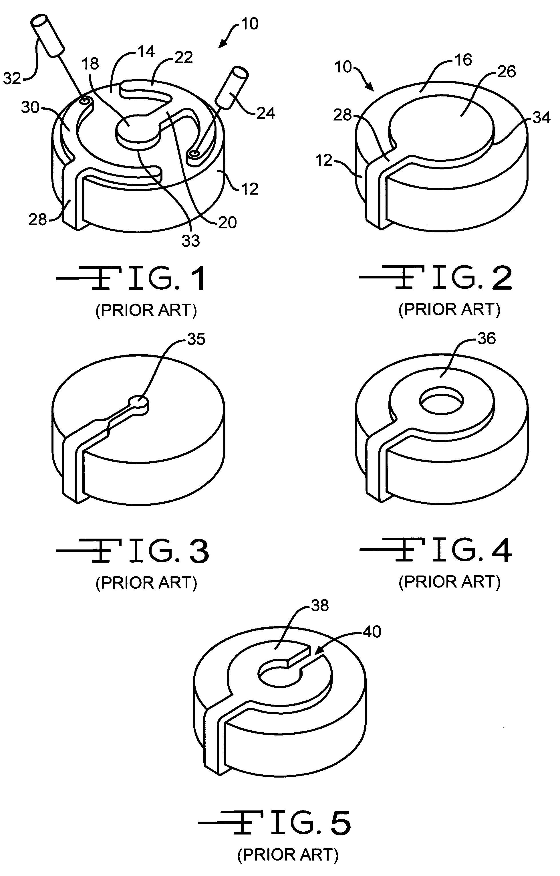
a lateral field and acoustic wave technology, applied in the field of acoustic wave sensors, can solve the problems of limited use of conventional qcm sensors, such as the one, fig. 1 and 2

Active Publication Date: 2006-07-11
UNIVERSITY OF MAINE
View PDF18 Cites 23 Cited by
  • Summary
  • Abstract
  • Description
  • Claims
  • Application Information

AI Technical Summary

Problems solved by technology

The use of conventional QCM sensors, such as the one shown in FIGS. 1 and 2, is limited to applications where measurand electrical properties such as permittivity and conductivity change in addition to changes in the mechanical properties listed above.

Method used


Image

  • Lateral field excited acoustic wave sensor
  • Lateral field excited acoustic wave sensor
  • Lateral field excited acoustic wave sensor

Examples


Embodiment Construction

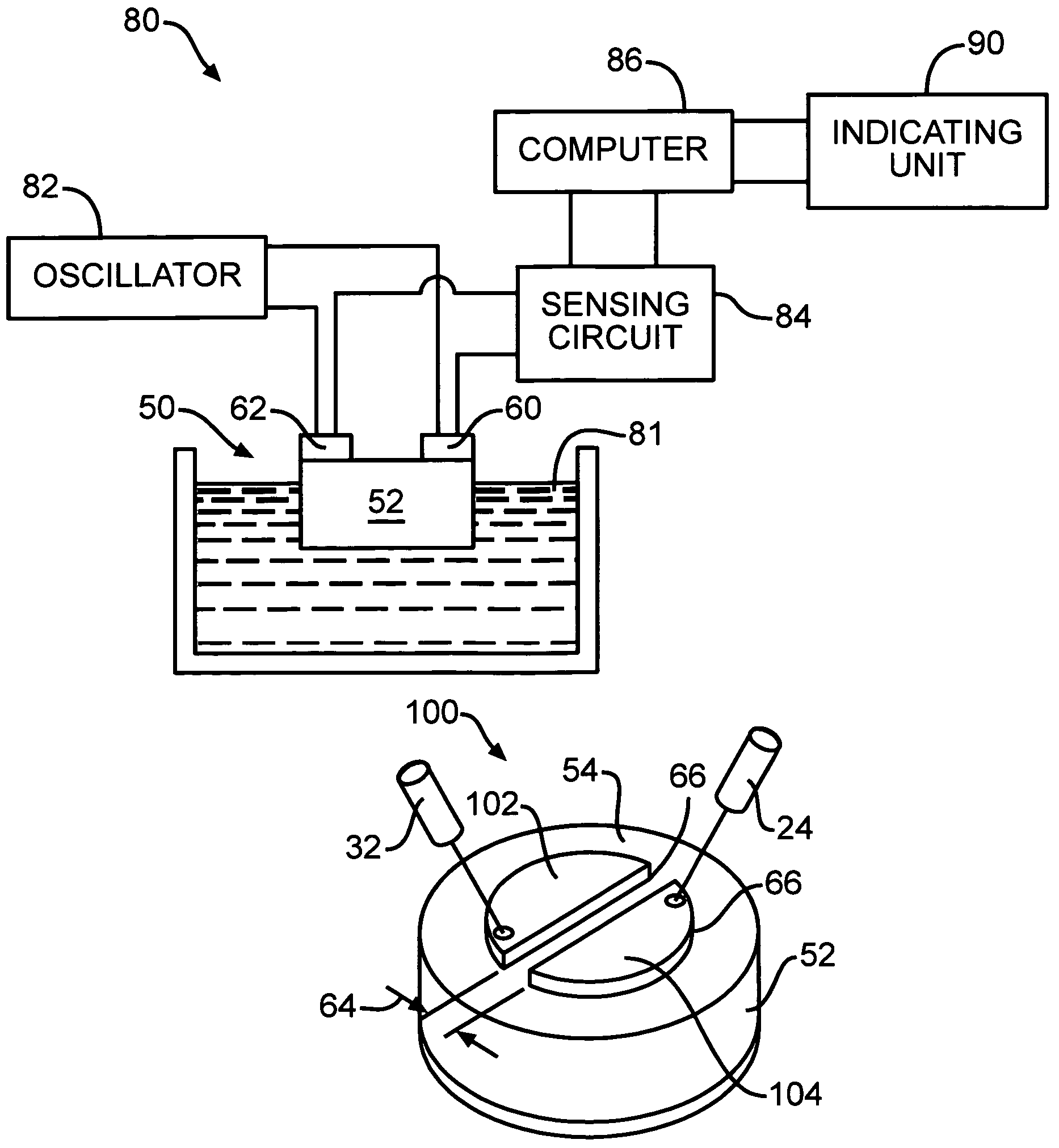
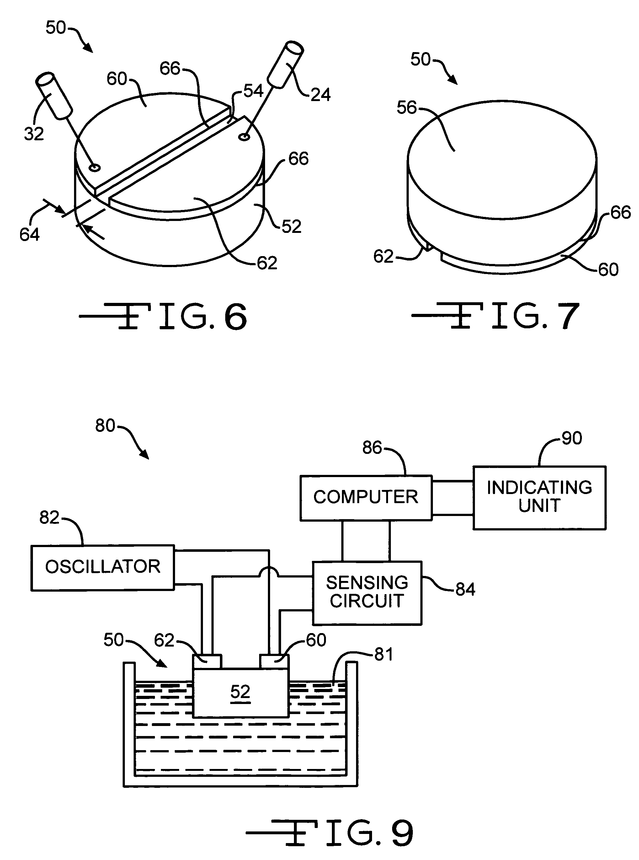
[0037]Referring again to the drawings, there is illustrated in FIGS. 6 and 7 a lateral field excited liquid acoustic sensor 50 that is in accordance with the invention. The sensor 50 includes a disc shaped substrate 52. In the preferred embodiment, AT-cut quartz crystal is used for the substrate. However, any crystal with a corresponding crystographic orientation that is capable of exciting only a Transverse Shear Mode (TSM) acoustic wave may be used, such as, for example, a crystal selected from the LGX family of crystals also may be utilized. The LGX family of crystals are materials of the trigonal crystal class 32, which is the same crystal class as quartz. The LGX family of crystals includes langatate (LGT, La3Ga5.5Ta0.5O14), langasite (LGS, La3Ga5SiO14), langanite (LGN, La3Ga5.5Nb0.5O14), and variations, such as LGTS (La3Ga5.25Ta0.25Si0.5O14) and LGZS (La3Ga5Zr0.5Si0.5O14). Additionally, the substrate also may be formed from Lithium Tantalate (LiTaO3) or Lithium Niobate (LiNbO3...


PUM


Abstract

An acoustic wave sensor having a piezoelectric substrate shaped to generate lateral electric fields. The sensor has a pair of electrodes deposited upon a reference surface of the substrate. A sensing surface that is opposite from the reference surface is adapted to be immersed in an environment, such as a gas or a liquid.

Description

STATEMENT REGARDING FEDERALLY SPONSORED RESEARCH OR DEVELOPMENT[0001]Research sponsored by Maine Sea Grant / NOAA No. NA16RG1034 and by National Science Foundation Grant No. EEC9820332.CROSS-REFERENCE TO RELATED APPLICATIONS[0002]Not ApplicableREFERENCE TO A SEQUENCE LISTING, A TABLE, OR A COMPUTER PROGRAM LISTING COMPACT DISC APPENDIX[0003]Not ApplicableBACKGROUND OF THE INVENTION[0004]This invention relates in general to acoustic wave sensors and in particular to a lateral field excited acoustic wave sensor.[0005]Piezoelectric materials, such as crystalline quartz, generate an electric field or voltage when subjected to mechanical stress and, conversely, generate mechanical stress when subjected to an electric field or voltage. Accordingly, piezoelectric materials have proven useful in many diverse technologies. Typically, electrodes are deposited upon the surface of the crystal and an AC voltage is applied to the electrodes to generate an electric field in the crystal. The electric...

Claims


Application Information

Patent Timeline
Patent Type & Authority Patents(United States)
IPC IPC(8): H01L41/08H04R17/00H01L41/00
CPCG01H11/08
Inventor VETELINO, JOHN F.
Owner UNIVERSITY OF MAINE
Why Eureka
Try Eureka