Liquid crystal display device, liquid crystal controller and video signal transmission method

a liquid crystal display device and controller technology, applied in static indicating devices, television systems, instruments, etc., can solve the problems of unsatisfactory reliability of connections, inability to implement cog&woa lcd modules, and inability to connect to the network, etc., to achieve convenient control

Inactive Publication Date: 2006-07-11
AU OPTRONICS CORP
View PDF23 Cites 40 Cited by
  • Summary
  • Abstract
  • Description
  • Claims
  • Application Information

AI Technical Summary

Benefits of technology

[0012]To achieve the above objects, according to the present invention, driver ICs to which an input video signal is distributed are, to the greatest extent possible, cascade-connected to reduce the number of wiring lines leading to the individual drivers IC, so that the COG&WOA structure can be implemented. That is, a liquid crystal display device according to the present invention comprises: a liquid crystal cell which forms an image display area on a substrate; and a driver for applying a voltage to the liquid crystal cell based on an input video signal, wherein the driver includes a plurality of driver ICs that are mounted on the substrate and are cascade-connected using signal lines.
[0013]It is preferable that each of the driver ICs include an input pad and an output pad, and that, because the cascade connection can be easily carried out, among these driver ICs the output pad of a first driver IC be connected to the input pad of a second driver IC. Further, when an input pad and an output pad are located at the two ends of each driver IC, the lengths of the signal lines and of the clock lines, or the lengths of paired signal lines along which a differential signal is transmitted, can be easily matched, and the phase adjustment can be easily performed.
[0016]Furthermore, it is preferable that a low differential voltage signal be employed for the transmission of a video signal, and that one pair of lines (two lines) be used for video data, while another pair of lines (two lines) is used for a synchronization clock. As a result, a fast serial interface can be efficiently implemented.
[0018]The downstream driver IC of the driver receives the masking signal from the upstream driver IC, and applies a voltage to the liquid crystal cell in accordance with the input video signal. Then, the downstream driver IC can easily receive a video signal following the receipt of a command to receive succeeding data.
[0021]The driver further comprises a clock line and a power line which makes a cascade connection to the plurality of driver ICs. The WOA can be implemented by efficient provision of substrate wiring.
[0029]The video signal can be transmitted to the LCD driver by using a packet, and the plurality of driver ICs are controlled by a protocol that employs the header of the packet. Thus, all the driver ICs can be easily controlled without a special control input by the driver IC being required.

Problems solved by technology

That is, since it is difficult for the conventional technique to provide the wiring between the chips on the glass substrate, a line wiring section is formed on the adjacent printed circuit board so that video data can be transmitted through a bus that connects the chips.
However, with a conventional bus connection, a great number of video signals are input to the LCD source driver, and implementation of a COG&WOA LCD module can not be performed.
Further, since in this structure all the chips are connected directly to the FPC, the number of connection terminals is increased, and the reliability of the connections will not be satisfactory.
In addition, since multiple FPC connection terminals are provided between the chips, large gaps are required between the chips, and this makes it difficult to reduce the size of the device.

Method used


Image

  • Liquid crystal display device, liquid crystal controller and video signal transmission method
  • Liquid crystal display device, liquid crystal controller and video signal transmission method
  • Liquid crystal display device, liquid crystal controller and video signal transmission method

Examples


Embodiment Construction

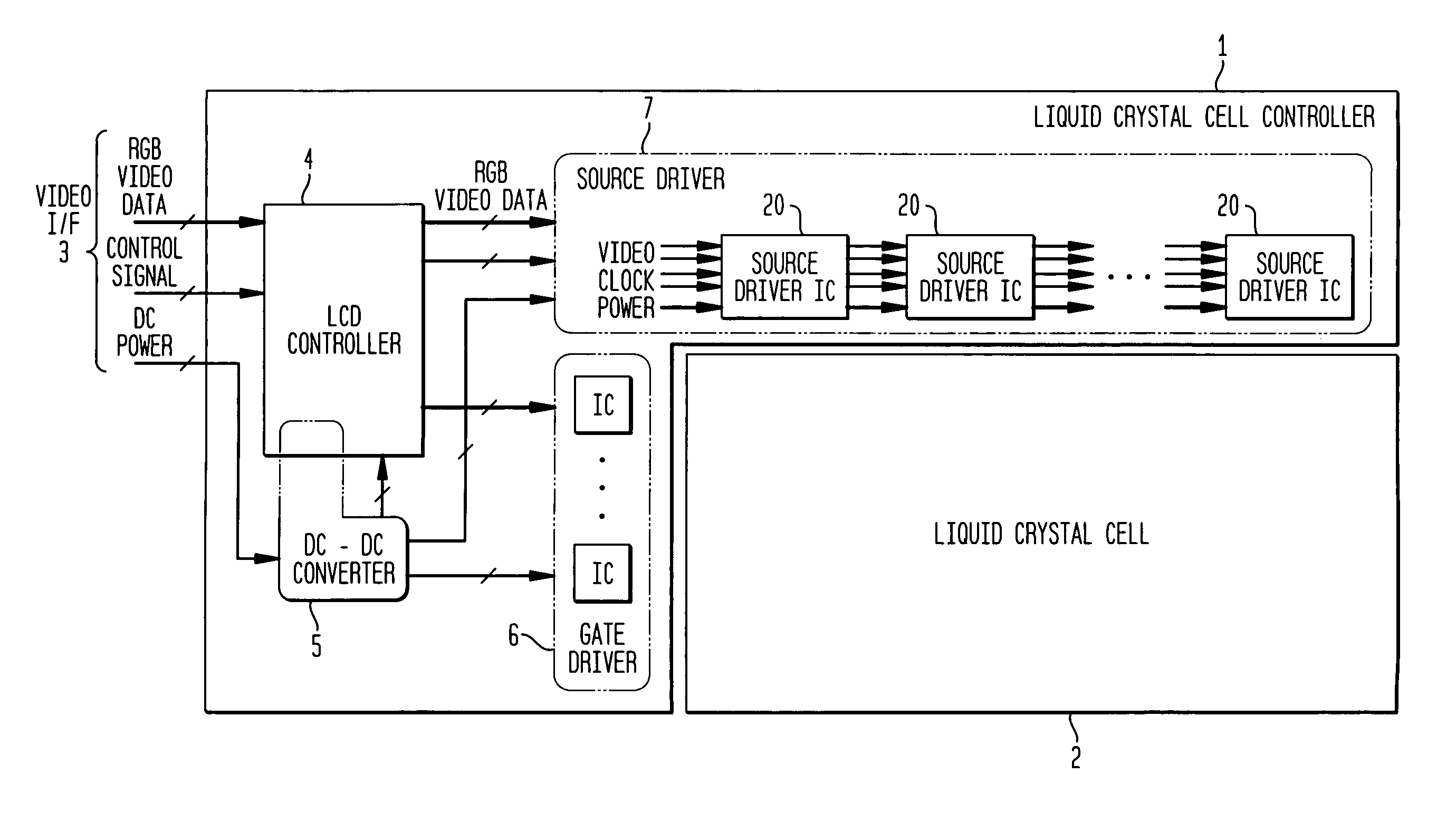
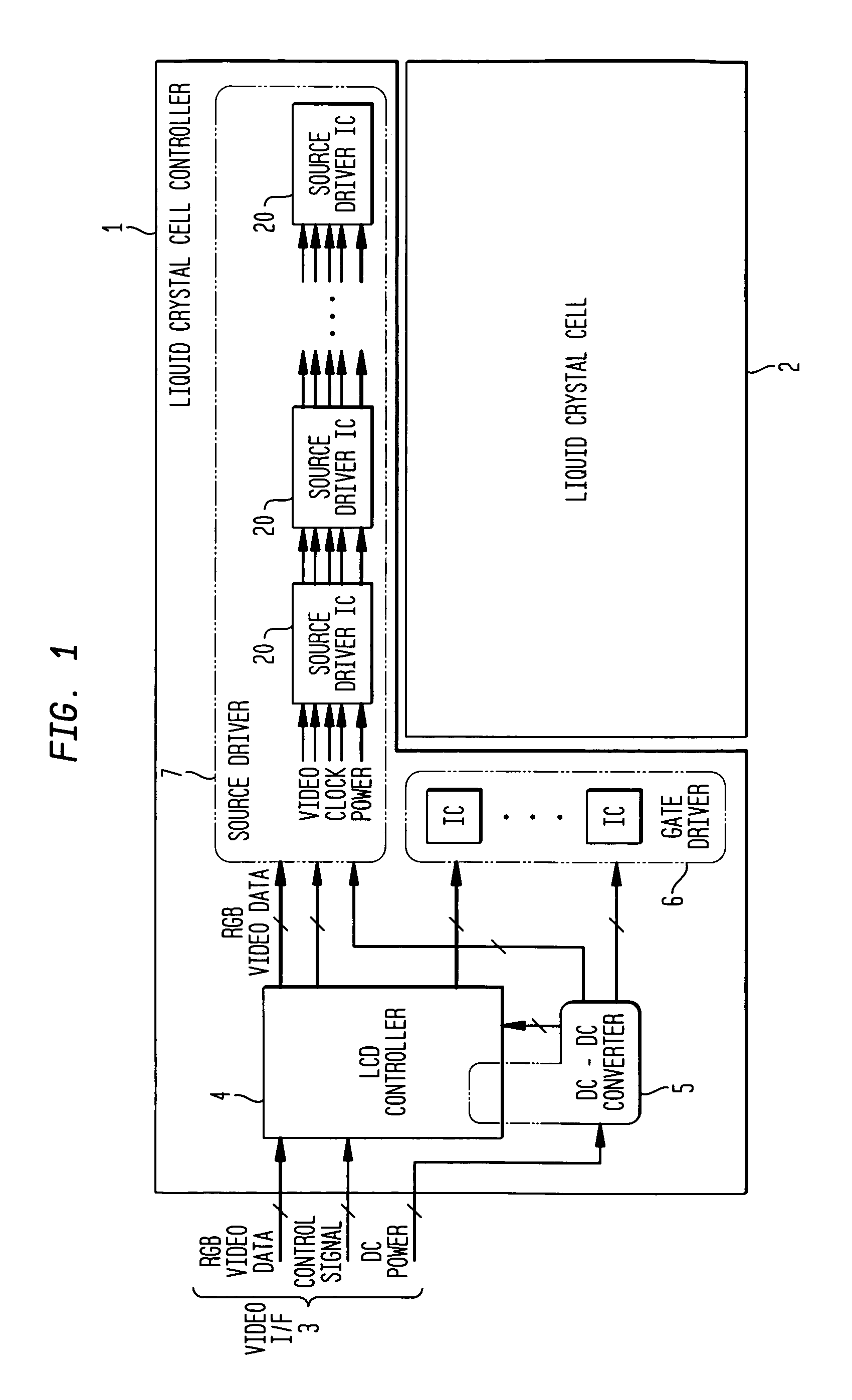
[0051]FIG. 1 is a diagram illustrating the arrangement of an image display device according to one embodiment of the present invention. A liquid crystal cell controller 1 and a liquid crystal cell 2, which has the same liquid crystal structure as does a thin-film transistor (TFT), constitute a liquid crystal module. The liquid crystal module is mounted on a display device that is separated from a host system, or on the display unit of a notebook PC. In the liquid crystal cell controller 1, RGB video data (video signals) or a control signal are transmitted by the graphics controller LSI (not shown), via a video interface (I / F) 3 of the host system, to an LCD controller 4. Further, generally, DC power is supplied via the video I / F 3. A DC—DC converter 5 employs the DC power that is received to generate a DC power voltage required by the liquid crystal cell controller 1, and supplies the voltage to a gate driver 6, a source driver 7, and a backlight fluorescent tube (not shown). The LC...


PUM

PropertyMeasurementUnit
clock frequencyaaaaaaaaaa
operating frequencyaaaaaaaaaa

Abstract

It is one object of the present invention to reduce the number of inputs to an LCD driver and to reduce manufacturing costs by employing the COG&WOA technique.For a liquid crystal display device, source driver ICs 20, among which video signals are transmitted and distributed via a video I / F 3, are cascade-connected, and the connection lines to the source driver ICs 20 are reduced as much as possible to employ the COG&WOA technique. That is, a liquid crystal display device comprises: a liquid crystal cell 2, which forms an image display area on a substrate, and a source driver 7, which applies a voltage to the liquid crystal cell 2 based on a video signal input via a video I / F 3. The source driver 7 includes a plurality of source driver ICs 20 that are mounted on the same substrate as the liquid crystal cell 2 and that are cascade-connected by signal lines.

Description

BACKGROUND OF THE INVENTION[0001]1. Technical Field[0002]The present invention relates to a liquid crystal display device for displaying an image based on a received video signal, and relates in particular to a liquid crystal display device provided with an improved driver interface for a liquid crystal display panel.[0003]2. Prior Art[0004]Generally, when displaying an image on a liquid crystal display panel, first, an image signal from the graphics controller of a system, including a PC, or of a system unit is output via a video interface. Then, upon receiving the image signal, an LCD (liquid crystal display) controller LSI transmits a signal to each of the individual ICs in a source driver (an X driver or an LCD driver) and a gate driver (a Y driver), and applies a voltage to each source electrode and each gate electrode in a TFT array, arranged as a matrix, until finally, an image is displayed.[0005]An interface used by a conventional LCD driver is shown in FIG. 20. In FIG. 20, ...

Claims


Application Information

Patent Timeline
Patent Type & Authority Patents(United States)
IPC IPC(8): G09G3/36G02F1/133G02F1/1345G09G3/20H04N5/66
CPCG09G3/3611G09G3/3688G09G2370/08G09G2310/027G09G2310/08G09G2300/0408G02F1/1345
Inventor SAKAGUCHI, YOSHITAMIDESGREZ, SIMON
Owner AU OPTRONICS CORP
Why Eureka
Try Eureka