Method for three-dimensional inspection using patterned light projection

a technology of patterned light and three-dimensional inspection, which is applied in the direction of optically investigating flaws/contamination, measurement devices, instruments, etc., can solve the problems of inaccurate measurement of insufficient inspection of three-dimensional electronic packages having specular surfaces with shape and height, and inability to accurately measure the lateral shift of the lines of the projected pattern

Inactive Publication Date: 2006-07-11
MICROSCAN SYSTEMS
View PDF13 Cites 18 Cited by
  • Summary
  • Abstract
  • Description
  • Claims
  • Application Information

AI Technical Summary

Benefits of technology

[0014]The patterned light projector also preferably includes a depth of focus modifier, for providing a lower f-number (i.e. less depth of focus) in a direction along a length of the lines of light projected on the surface of the article, and a higher f-number (i.e. greater depth of focus) in

Problems solved by technology

Existing systems and methods for three-dimensional inspection using projected light patterns, however, do not adequately provide an accurate inspection of three-dimensional electronic packages having specular surfaces with a shape and height, such as Ball Grid Array (BGA) devices or lead frames used in the manufacturing of electronic devices.
If the projected pattern or image is not properly focused or is distorted, measurements of the lateral shift in the lines of the projected pattern may not be accurate.
As a result, the width of the lines projected onto the article may not be consistent over the entire range of the article being inspected.
Existing patterned light projectors also encounter problems as a result of three-dimensional specular surfaces, such

Method used


Image

  • Method for three-dimensional inspection using patterned light projection
  • Method for three-dimensional inspection using patterned light projection
  • Method for three-dimensional inspection using patterned light projection

Examples


Embodiment Construction

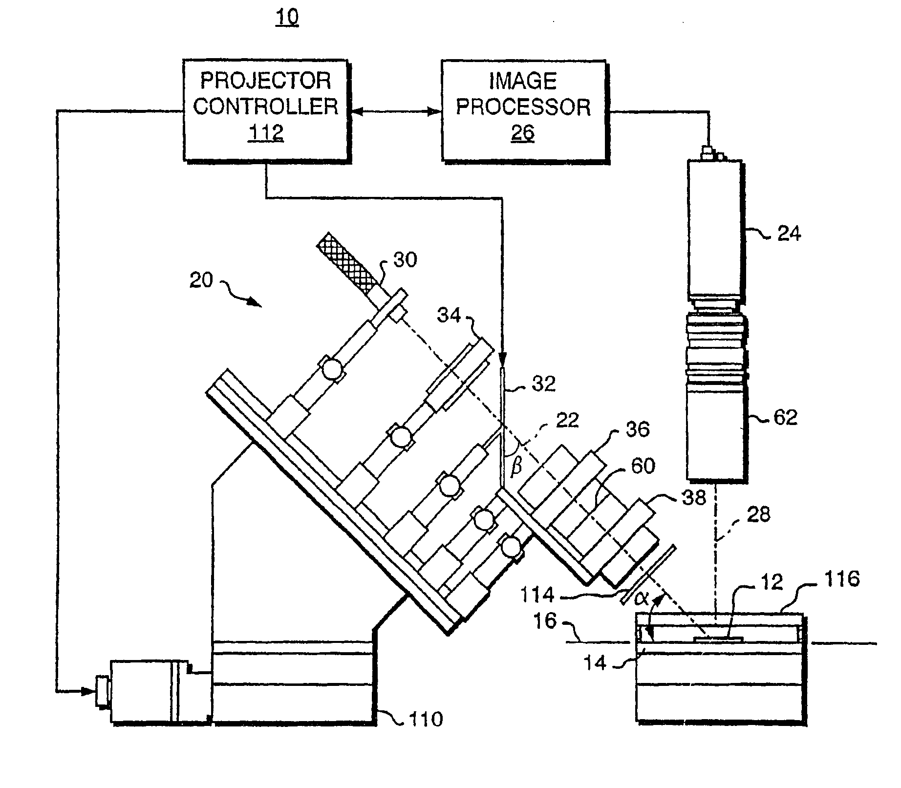
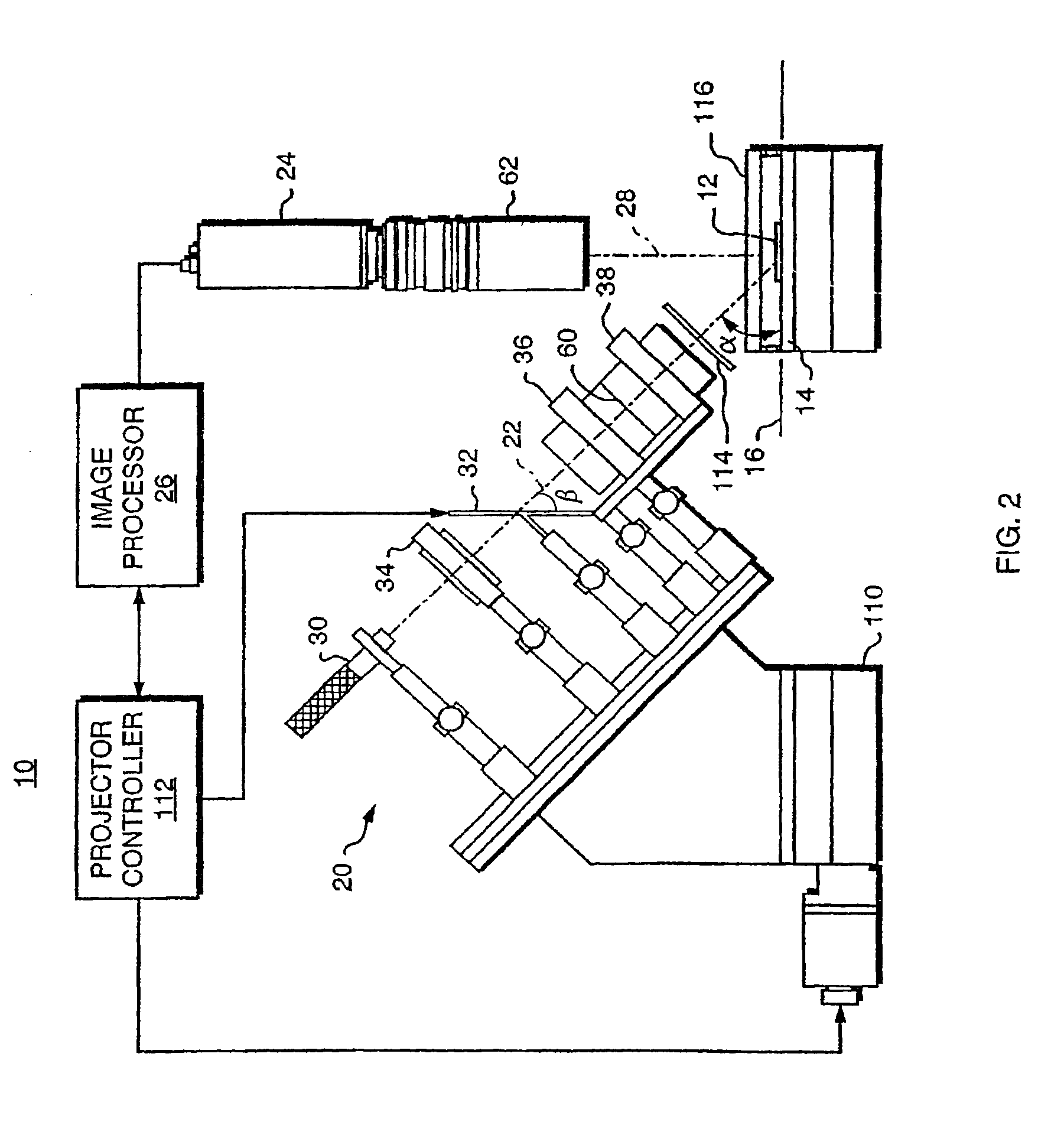
[0043]The three-dimensional inspection system 10, FIG. 2, according to the present invention, projects a light pattern, such as a pattern of lines, onto the surface of a three-dimensional article 12 to be inspected, such as a BGA device or lead frames used in the manufacturing of electronic devices, and analyzes the reflected light pattern to determine three-dimensional characteristics of the surface of the article three-dimensional 12. In general, the three-dimensional inspection system 10 includes an article support 14 that supports the three-dimensional article 12 generally in a plane 16, and a patterned light projector 20 that projects the pattern of light generally along an optical axis 22 onto the three-dimensional article 12 with the optical axis 22 of the projector 20 at an oblique angle α with respect to the plane 16 of the three-dimensional article 12. A light pattern (or image) detector 24, such as a CCD camera, detects the light pattern (or image) projected onto the thre...


PUM


Abstract

A three-dimensional inspection system and method is used to obtain information about three-dimensional articles with specular surfaces having a shape and positive or negative height by projecting a pattern of light onto the articles at an oblique angle. The system includes a patterned light projector with optical axis disposed at an oblique angle with respect to the plane of the article being inspected, an extended light source, and an image detector disposed above the article to detect the image of the pattern on the article. The light pattern includes lines with a substantially equal thickness and spacing. The spacing of the lines is greater than a spacing or pitch of the specular elements. An image processor, coupled to the image detector, receives the image, locates the lines, and measures the lateral shift of the lines. Height information is determined from the lateral shift and projection angle using triangulation.

Description

CROSS-REFERENCE TO RELATED APPLICATIONS[0001]This application is a continuation-in-part of U.S. patent application Ser. No. 09 / 150,716 filed Sep. 10, 1998 now U.S. Pat. No 6,262,803.STATEMENT OF GOVERNMENT SUPPORT[0002]This invention was made with Government support under Contract No. DAAH01-96-C-R208 awarded by the Department of the Army. The Government has certain rights in the invention.TECHNICAL FIELD[0003]The present invention relates to systems and methods for three-dimensional inspection of articles and more particularly, to a system and method for inspection of three-dimensional electronic packages using a projected pattern of light.BACKGROUND INFORMATION[0004]Projecting patterned or structured light onto an article is a well known technique for obtaining three-dimensional information pertaining to the article. As shown in FIG. 1, a projector 1 is used to project a pattern of light, such as a series of parallel lines 2, onto surfaces 4, and 6. The axis 3 of the projector 1 i...

Claims


Application Information

Patent Timeline
IPC IPC(8): G01B11/24G01N21/88
CPCG01N21/8806G01N21/88
Inventor HALLERMAN, GREGORY R.LUDLOW, JONATHAN E.STERN, HOWARD K.
Owner MICROSCAN SYSTEMS
Why Eureka
Try Eureka