
System for mixed signal synthesis

Inactive Publication Date: 2006-07-11
CADENCE DESIGN SYST INC
View PDF28 Cites 45 Cited by
  • Summary
  • Abstract
  • Description
  • Claims
  • Application Information

AI Technical Summary

Benefits of technology

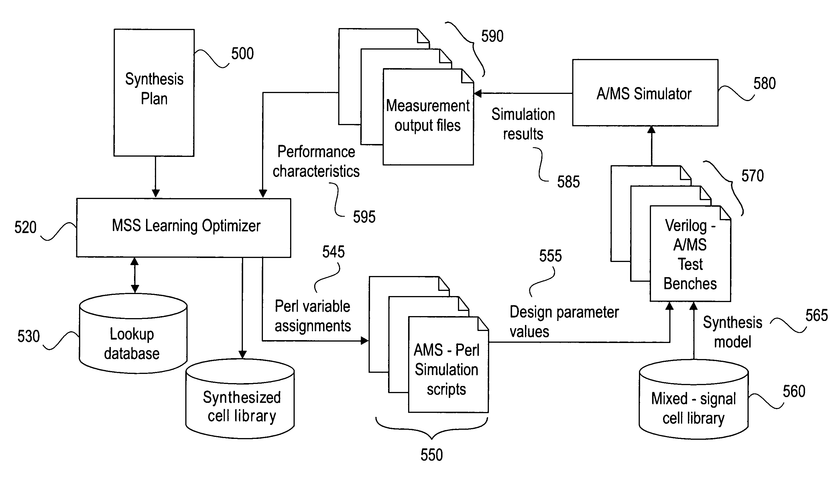
[0030]Furthermore, many of the programming instructions in existing electronic design automation programs involve the transformation of data from one specific format into another specific format in order to pass the design data from program to program. These programs spend a great deal of their time reconstructing information internally and then simply ignoring that information when it comes time to generate output for the next tool in the flow. The present invention, by taking advantage of the information inherent in the design data, reduces the amount of time performing operations again and again inside each tool, leading to increased performance and a reduced chance of error.

Problems solved by technology

However, commercially available tools do not provide true synthesis of analog or mixed analog regardless of the underlying description languages or simulators.

Method used


Image

  • System for mixed signal synthesis
  • System for mixed signal synthesis
  • System for mixed signal synthesis

Examples


example 1

---------

‘language SPICE

.include / usr / tools / antrim / Mss / scl / Models / bsim3 / model.typ

.SUBCKT delay_ibias INN INP OUTN OUTP control VSS VDD

+lnb=1u wnb=1.1u lpdiff=0.6u wpdiff=8u ibias=50u

M0 OUTN control VSS VSS NMOS_MOD L=“lnb”, W=“wnb”

+AD=10P AS=4P PD=9.0U PS=3.6U NRD=0.3 NRS=0.3

M1 OUTP control VSS VSS NMOS_MOD L=“lnb” W=“wnb”

+AD=4P AS=10P PD=3.6U PS=9.0U NRD=0.3 NRS=0.3

M2 tail INN OUTP VDD PMOS_MOD L=“lpdiff” W=“wpdiff” NRD=0.3 NRS=0.3

M3 tail INN OUTP VDD PMOS_MOD L=“lpdiff” W=“wpdiff” NRD=0.3 NRS=0.3

M4 tail INP OUTN VDD PMOS_MOD L=“lpdiff”, W=“wpdiff” NRD=0.3 NRS=0.3

M5 tail INP OUTN VDD PMOS_MOD L=“lpdiff” W=“wpdiff” NRD=0.3 NRS=0.3

ibias vdd tail dc “ibias”

.ENDS CELL

‘endlanguage

Modeling of Performance Characteristics

[0155]After the netlist has been parameterized, the designer decides what the performance characteristics are and develops the model for each performance characteristic.

[0156]There are several methods of behavioral modeling for synthesis, including:

[0157]1. Polynomial equa...

example 2

----------

‘timescale 100 ps / 10 ps

‘include “disciplines.h”

‘include “connect.h”

module top;

[0164]electrical ground, inn1, inp1, outn1, outp1, outn2, outp2, vctrl, vdd;

[0165]electrical outn3, outp3, outn4, outp4, outn5, outp5, outn6, outp6;

[0166]electrical outn7, outp7;

[0167]delay_ibias cell1(inn1, inp1, outn1, outp1, vctrl, ground, vdd);

[0168]delay_ibias cell2(outp1, outn1, outn2, outp2, vctrl, ground, vdd);

[0169]delay_ibias cell3(outp2, outn2, outn3, outp3, vctrl, ground, vdd);

[0170]delay_ibias cell4(outp3, outn3, outn4, outp4, vctrl, ground, vdd);

[0171]delay_ibias cell5(outp4, outn4, outn5, outp5, vctrl, ground, vdd);

[0172]delay_ibias cell6(outp5, outn5, outn6, outp6, vctrl, ground, vdd);

[0173]delay_ibias cell7(outp6, outn6, outn7, outp7, vctrl, ground, vdd);

[0174]delay_ibias cell8(outp7, outn7, inn1, inp1, vctrl, ground, vdd);

[0175]frequency #(.trig(0.25), .occ(100), .dir(1), .filename(“freq.meas”)) meas1(inn1);

[0176]power #(.ibias(4.951908e−05)) meas2( );

[0177]vdc_source #(.vdc(5.0...


PUM


Abstract

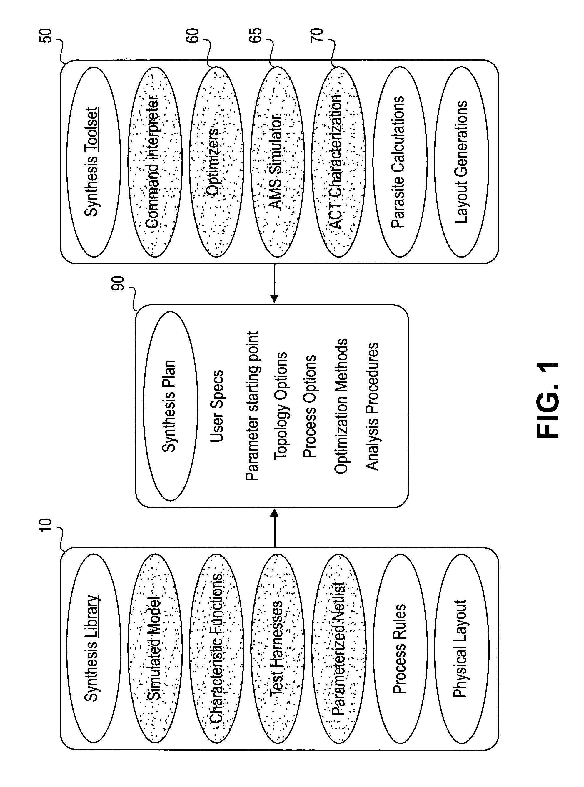
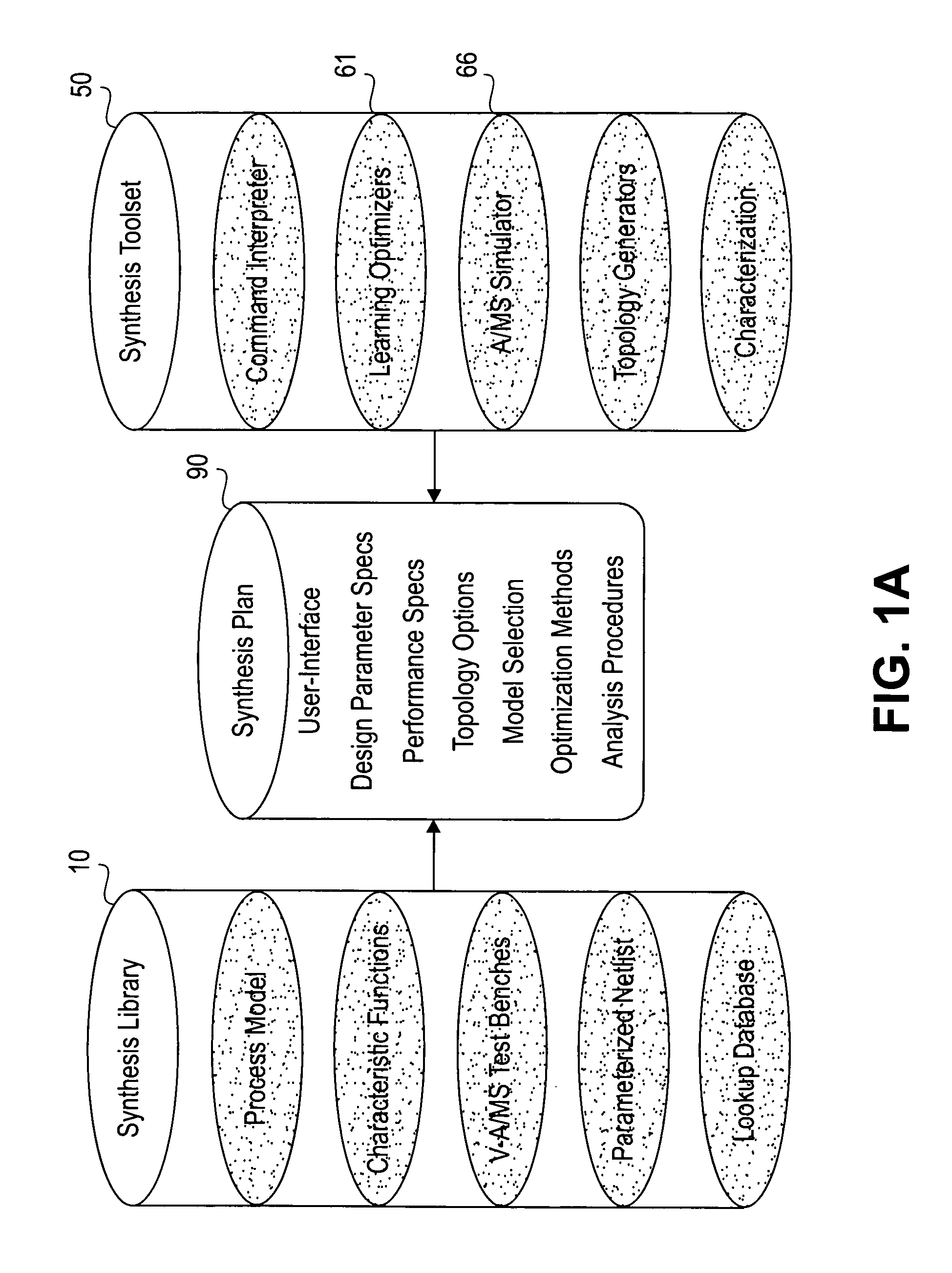
Circuit synthesis is performed utilizing an optimizer that selects design parameters for a synthesis model of a circuit based on desired performance characteristics and performance characteristics / design parameters of previously synthesized circuits. Performance characteristics and design parameters of each synthesized circuit are maintain in conjunction with the synthesis model of the circuit being synthesized. A synthesis plan identifies the synthesis model and specific instructions on how to perform optimized selection of design parameters, how to set up test benches, and how to perform the simulation.

Description

[0001]This application is a continuation-in-part of Ser. No. 09 / 216,752, filed Dec. 17, 1998 now U.S. Pat. No. 6,356,796, now U.S. Pat. No. 6,356,796 entitles “LANGUAGE CONTROLLED DESIGN FLOW FOR ELECTRONIC CIRCUITS”. Additionally, this application claims priority to each of the following provisional patent applications:[0002](1) Demler, a provisional patent application Ser. No. 60 / 140,108, filed Jun. 18, 1999, entitled “MIXED SIGNAL SYNTHESIS,”[0003](2) Demler, a provisional patent application Ser. No. 60 / 162,736, filed Oct. 29, 1999, entitled “MIXED SIGNAL SYNTHESIS (MSS) ADDENDUM,” and[0004](3) Ellis et al., a provisional patent application Ser. No. 60 / 164,220, filed Nov. 9, 1999, entitled “LEARNING MODE OPTIMIZATION,” each of which are incorporated herein by reference, in their entirety.COPYRIGHT NOTICE[0005]A portion of the disclosure of this patent document contains material which is subject to copyright protection. The copyright owner has no objection to the facsimile reprodu...

Claims


Application Information

Patent Timeline
IPC IPC(8): G06F17/50
CPCG06F17/505G06F17/5054G06F2217/86G06F30/34G06F30/327G06F2117/08G06F30/347
Inventor DEMLER, MICHAEL J.LIM, STEPHENELLIS, GEOFFREYSPRUIELL, LESLIE D.MCGUFFIN, ROBERT W.SORENSEN, BENT H.
Owner CADENCE DESIGN SYST INC
Learn More