Damping intermediate pillar and damping structure using the same

a technology of damping structure and intermediate pillar, which is applied in the direction of building components, building types, constructions, etc., can solve the problems of insufficient strength of joins and lack of endurance, and achieve the effects of increasing the shearing deformation of viscoelastic materials, and reducing the number of shearings

Inactive Publication Date: 2006-07-18
KAZUHIKO KASAI +1
View PDF45 Cites 41 Cited by
  • Summary
  • Abstract
  • Description
  • Claims
  • Application Information

AI Technical Summary

Benefits of technology

[0018]According to this invention, in addition to the joins for fixing a damping intermediate pillar by welding or bolting to the beams of the upper and lower floors, knee braces or reinforcing ribs are used to couple one or both sides of the damping intermediate pillar or the coupling members to the beams of the upper and lower floors, thereby improving the strength of the joins, as a whole, between the damping intermediate pillar and the beams. Therefore, a sufficient resistance can be exhibited, with comparative ease, against a large horizontal force acting on a building at the time of an earthquake of a large magnitude. Also, the use of the knee braces or the reinforcing ribs for coupling increases the shearing deformation of the viscoelastic material, thereby making it possible to absorb a larger amount of vibration energy.

Problems solved by technology

The conventional join structure between the upper and lower end portions of the damping intermediate pillar and the upper and lower floor beams, however, poses the following problem as it lacks the strength of endurance of the join between the damping intermediate pillar 4 and the upper and lower floor beams 3a, 3b against the horizontal force which may be exerted by an earthquake.
In view of the fact that the upper and lower end portions of the damping intermediate pillar 4 are fixedly coupled simply by bolts or welding to the beams 3a, 3b of the upper and lower floors, however, the join strength is not sufficient against an earthquake of a comparatively large magnitude.

Method used


Image

  • Damping intermediate pillar and damping structure using the same
  • Damping intermediate pillar and damping structure using the same
  • Damping intermediate pillar and damping structure using the same

Examples


Embodiment Construction

[0051]Embodiments of the invention will be explained in detail below with reference to the accompanying drawings.

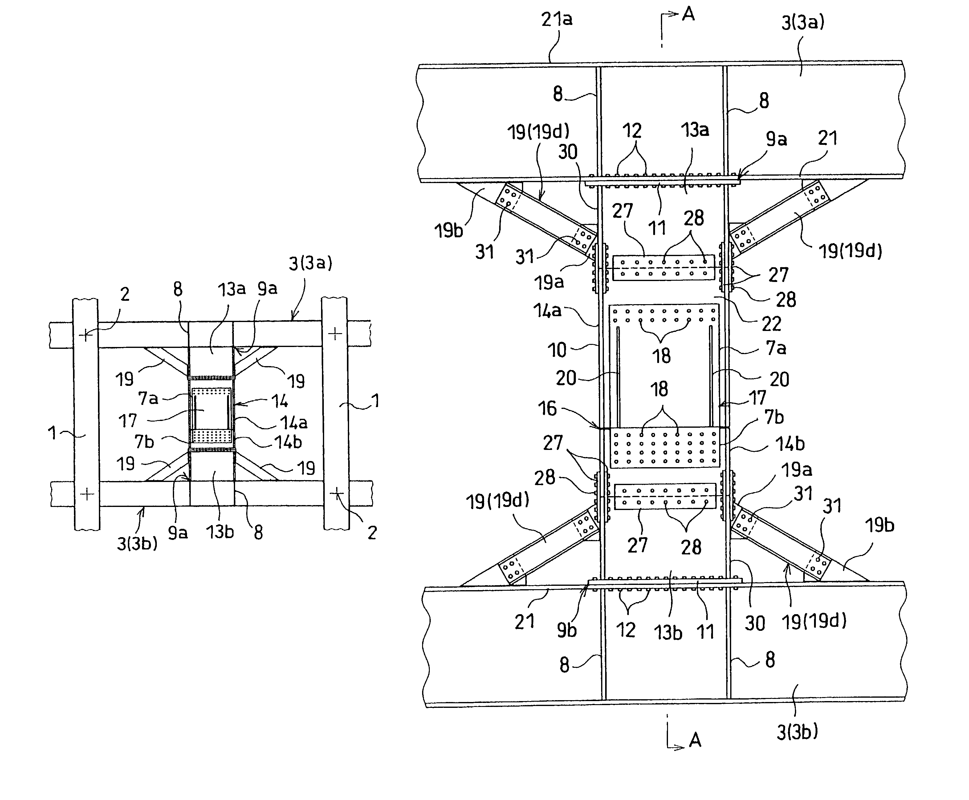
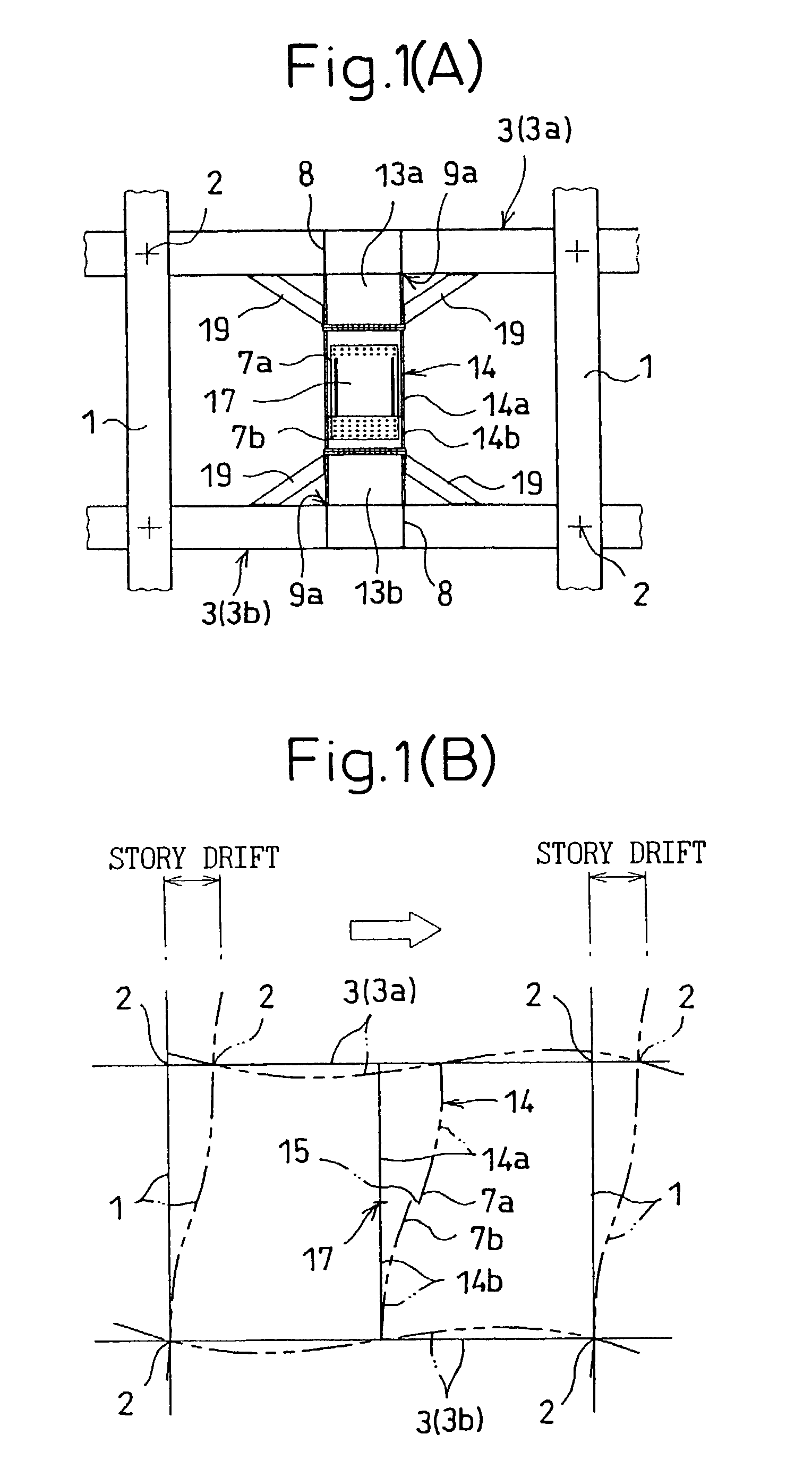
[0052]FIGS. 1 to 4 show a first embodiment of the invention, in which FIGS. 1A and 1B, corresponding to FIGS. 23A and 23B for explaining the prior art, are diagrams schematically showing the structural arrangement of a damping intermediate pillar having a viscoelastic damper built therein for explaining the attenuation effect of the structural frame of a building.

[0053]In FIG. 1, the structural frame of the building includes a pillar 1 of a rectangular steel pipe filled with concrete and beams 3 of H shape steel coupled to each other by pillar-beam joins 2. The structure also includes a damping intermediate pillar 14 having a viscoelastic damper 17 arranged between the beams 3a and 3b of the upper and lower floors. The structure for fixing the damping intermediate pillar 14 and the beams 3 is different from that of the prior art.

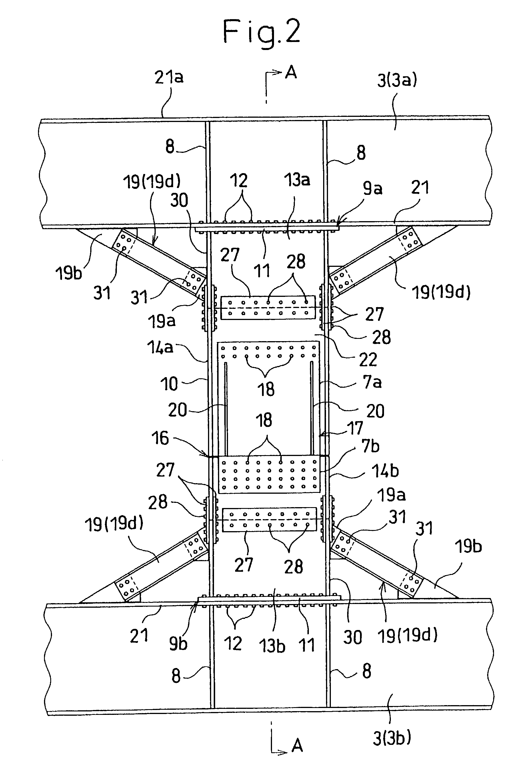
[0054]FIGS. 2 to 4 show a detailed structur...


PUM


Abstract

A damping intermediate pillar, which can exhibit a sufficient resistance against the horizontal force of a strong earthquake by reinforcing the joins between the damping intermediate pillar and the upper and lower beams, is disclosed. A damping intermediate pillar 14, used for a building or a structure configured of pillars 1 and beams 3, is divided into upper and lower damping intermediate pillar portions 14a, 14b of H shape steel, and includes a plurality of inner steel plates 7b fixed on the damping intermediate pillar portion 14b and a plurality of outer steel plates 7a fixed on the other damping intermediate pillar portion 14a. The inner and outer steel plates are arranged alternately in a single or a plurality of layers, between which a viscoelastic member 15 is held to make up a viscoelastic damper 17. The coupling end surfaces of the intermediate pillar portions 14a, 14b directed vertically are fixed on the upper and lower floor beams 3a, 3b. Further, one or both sides of each of the damping intermediate pillar portions 14a, 14b (i.e. the coupling members 13a, 13b) and the upper and lower floor beams 3a, 3b are coupled to each other by knee braces 19.

Description

BACKGROUND OF THE INVENTION[0001]1. Field of the Invention[0002]The present invention relates to a damping intermediate pillar and a damping structure using such a damping pillar intended to absorb an input vibration energy or, especially, a horizontal force in framed structures and various other structures of buildings.[0003]2. Description of the Related Art[0004]The conventional techniques in this category include the following (1) to (7):[0005](1) Japanese Unexamined Patent Publication No. 2000-274108 relating to a structure of a viscoelastic damper coupled directly to the beams of upper and lower floors, (2) Japanese Unexamined Patent Publication No. 2000-54680 relating to a detailed structure for installing a viscoelastic damper on the beams of upper and lower floors, (3) Japanese Unexamined Patent Publication No. 2000-73605 relating to the surface shape of a laminated steel plate for a viscoelastic damper, (4) Japanese Unexamined Patent Publication No. 2000-73608 relating to a...

Claims


Application Information

Patent Timeline
Patent Type & Authority Patents(United States)
IPC IPC(8): E04H9/02E04B1/98E04B1/24F16F15/04
CPCE04H9/02E04B2001/2415E04B2001/2442E04B2001/2448E04B2001/2445E04H9/0237
Inventor KASAI, KAZUHIKONAKAMURA, HIROSHINAKATA, YASUHIROSHIRAI, TAKASHI
Owner KAZUHIKO KASAI
Why Eureka
Try Eureka