Enclosure for handling hazardous material

a technology for enclosings and hazardous materials, applied in the direction of positive displacement liquid engines, piston pumps, instruments, etc., can solve the problems of inability to provide a suitable evacuated environment, inability to provide vacuum, and inability to portability and sophisticated filtering mechanisms for bio-hazardous materials

Active Publication Date: 2006-07-18
TATTERSHALL STEPHEN F
View PDF15 Cites 18 Cited by
  • Summary
  • Abstract
  • Description
  • Claims
  • Application Information

AI Technical Summary

Benefits of technology

[0008]It is an object of the present invention to provide an enclosure for handling hazardous materials in which hazardous material and suspect material can be safely handled without fear of contamination of the technician, the surrounding atmosphere, or the operational area in which the work enclosure is used.
[0009]It is another object of the present invention to provide an enclosure for handling hazardous material which is relatively economical.
[0012]It is still another object of the invention to provide an enclosure for handling hazardous material which meets federal regulatory standards for dealing with hazardous material in a relatively inexpensive manner.
[0013]It is a further object of the invention to provide an enclosure for handling hazardous material which is user friendly having a simple visual confirmation that a relatively sealed environment exists.
[0015]It is another object to provide an enclosure for handling hazardous material which is relatively lightweight and manually portable, attractive, reliable in use, requires minimum maintenance, provides maximum safety to the user, and yet is of a simple design which can be readily and inexpensively manufactured.

Problems solved by technology

Prior hereto, the devices for handling bio-hazardous materials used relatively non-portable vented hoods and sophisticated filtering mechanisms.
Inexpensive mail opening devices for consumer and office use which exist provide containment, but are inadequate in their ability to provide a suitable evacuated environment.
For example, glove bags exist for portable clean-up or inspection, but provide no vacuum.

Method used


Image

  • Enclosure for handling hazardous material
  • Enclosure for handling hazardous material
  • Enclosure for handling hazardous material

Examples


Embodiment Construction

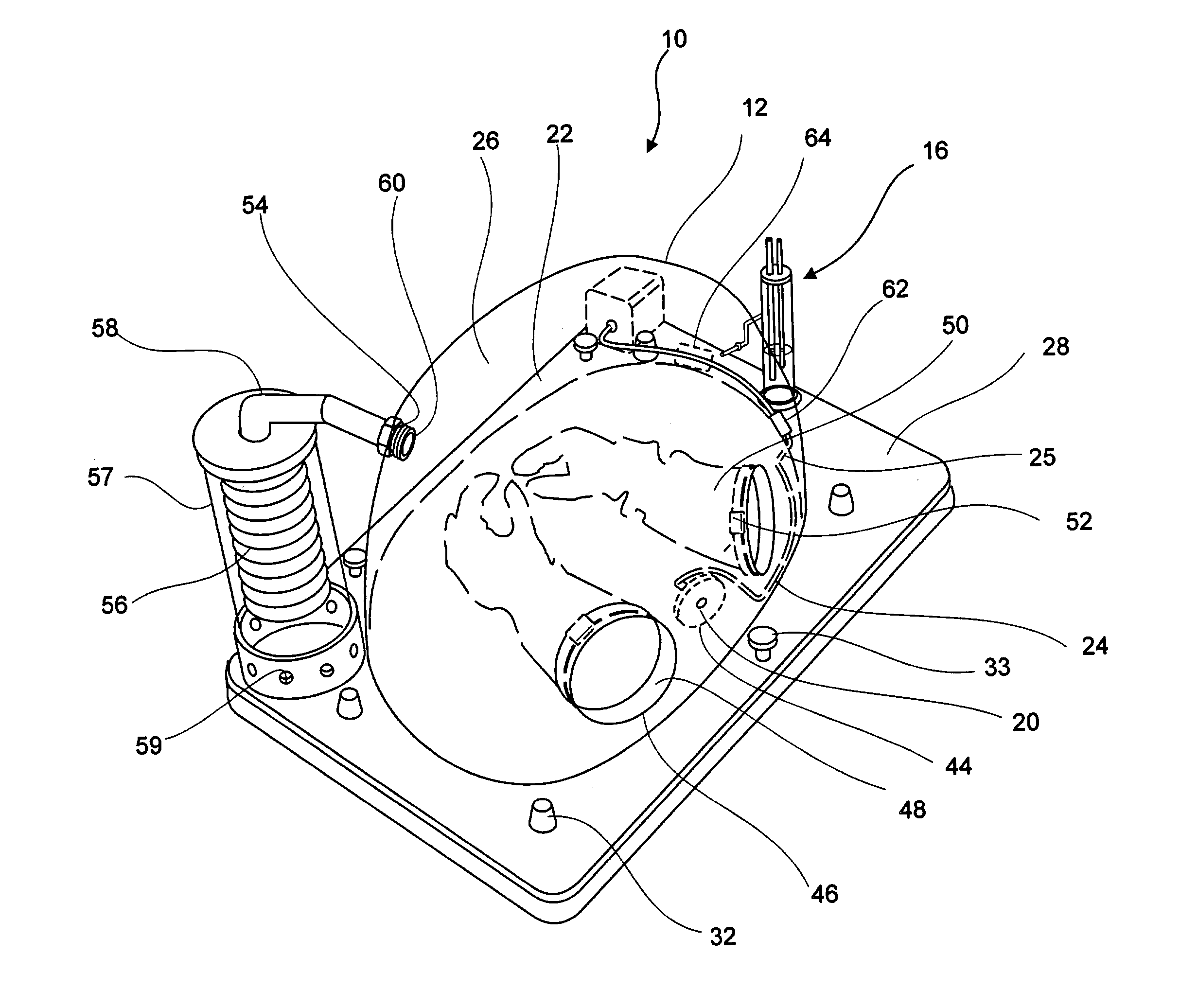
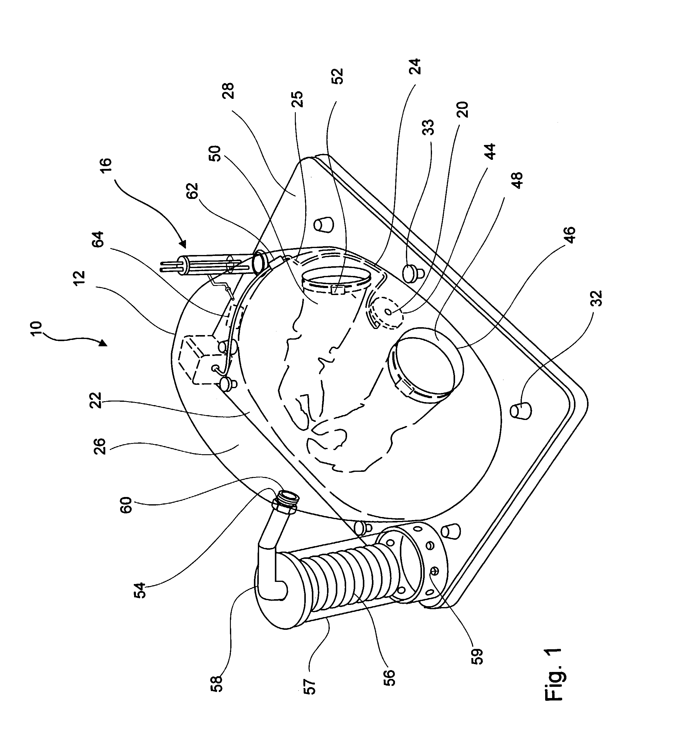
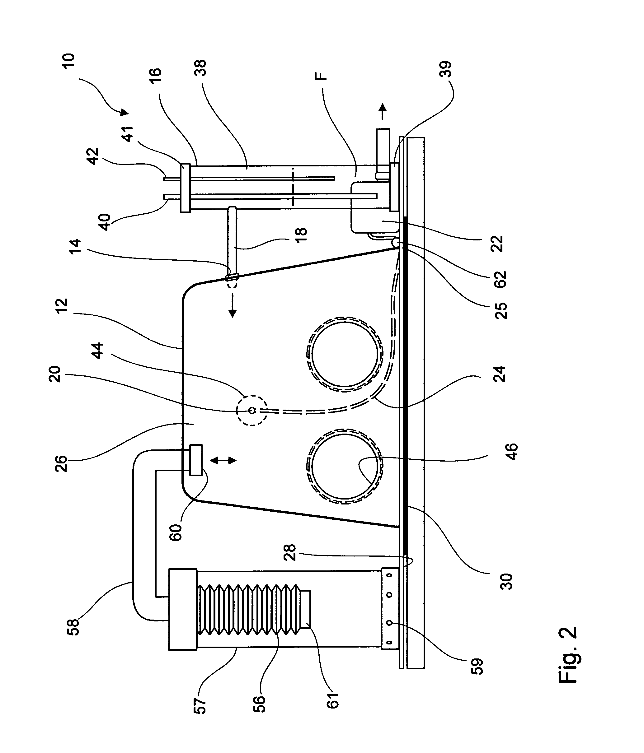
[0025]Referring now to the drawings, the present invention is directed to an enclosure for handling hazardous and suspect material which is generally designated by the numeral 10. The enclosure 10 includes a sealable housing 12 which is configured with an air inlet 14 which is connected to a bubble gauge 16 via a conduit 18.

[0026]An air inlet 20 is disposed inside the housing 12 and is for air evacuation from the housing 12 and operably connects to a pump 22 via a conduit 24 for maintaining subatmospheric pressure in the enclosure 10 and for drawing a stream of air inwardly through the air inlet 14 via the bubble gauge 16 into the housing 12 and out the air inlet 20. The conduit 24 is press fit through an open surface 25 in the housing 12. The pump 22 can be an electric diaphragm pump—24 VAC×UL transformer having a power consumption of 3 Watts and provide sufficient suction to maintain flow rate between 0.5 to 1.5 liters / min.

[0027]The housing 12 can preferably include a transparent ...


PUM


Abstract

An enclosure for handling hazardous material includes a sealable housing which is configured with a first air inlet connected to a bubble gauge and a second air inlet disposed inside the housing for air evacuation from the housing is connected to a pump for maintaining subatmospheric pressure in the enclosure and for drawing a stream of air inwardly through the first air inlet via the bubble gauge into the housing and out the second air inlet. A filter interposed in the stream of air leading to the second inlet. At least one glove port is formed in the housing and has a flexible relatively gas impermeable glove connected thereto. An air exchange port in the housing is operably connected to a sealed bellows which provides for changes in air volume within the enclosure which occurs from moving the glove within the enclosure under subatmospheric pressure.

Description

BACKGROUND OF THE INVENTION[0001]1. Field of the Invention[0002]The present invention relates to enclosures for handling hazardous material. More specifically, the invention is directed to an evacuated enclosure which is used for handling, inspecting or processing hazardous materials, irritating substances or articles or containers known or suspected of containing the same.[0003]2. Discussion of the Art[0004]There previously exist a number of enclosures for handling chemical, nuclear or bio-hazardous material in a self contained environment. These enclosures are commonly employed in industrial laboratory environments.[0005]Recently, national concerns over health hazards resulting from bio-hazardous mail, chemical weapons, or nuclear materials, require the use of a contained environment for handling suspect mail and other objects. Prior hereto, the devices for handling bio-hazardous materials used relatively non-portable vented hoods and sophisticated filtering mechanisms. Current ma...

Claims


Application Information

Patent Timeline
Patent Type & Authority Patents(United States)
IPC IPC(8): A61G11/00
CPCB01L1/50B25J21/02B01L2400/049
Inventor TATTERSHALL, STEPHEN F.
Owner TATTERSHALL STEPHEN F
Why Eureka
Try Eureka