Deployable recoverable vascular filter and methods for use

a vascular filter and recovery technology, applied in the field of vascular filters, can solve the problems of affecting the patient's health, affecting the structure of the filter itself, and damage to the vessel intima, so as to reduce the risk of damage to the filter, and be easy to introdu

Inactive Publication Date: 2006-07-18
ENDOTEX INTERVENTIONAL SYST
View PDF15 Cites 43 Cited by
  • Summary
  • Abstract
  • Description
  • Claims
  • Application Information

AI Technical Summary

Benefits of technology

[0017]An important feature of the present invention is that the vascular filter, when deployed within a blood vessel, slidably engages the guidewire used to deliver it. When subsequent devices are advanced over the guidewire, they may cause the guidewire to move back and forth within the vessel, but may not affect the deployed vascular filter, as the guidewire may simply slide back and forth within the tubular member. Thus, this slidable arrangement substantially reduces the risk of damage to the vessel that may be caused by inadverten

Problems solved by technology

One of the problems with these procedures, however, is that embolic material may be released from the wall of the vessel during the procedure, and travel downstream where it may become lodged or otherwise cause harm to the patient.
This movement of the filter may damage the vessel intima, may release em

Method used


Image

  • Deployable recoverable vascular filter and methods for use
  • Deployable recoverable vascular filter and methods for use
  • Deployable recoverable vascular filter and methods for use

Examples


Embodiment Construction

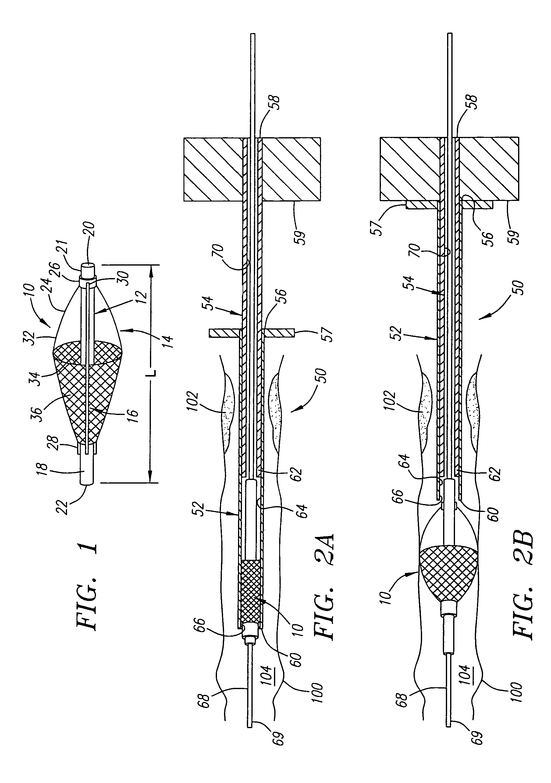
[0026]Turning now to the drawings, FIG. 1 shows a preferred embodiment of a vascular filter 10 in accordance with one aspect of the present invention. The vascular filter 10 generally includes an elongate tubular member 12, an expandable frame 14 disposed on the tubular member 12, and filter material 16 attached to the expandable frame 14 and / or the tubular member 12.

[0027]The tubular member 12 is preferably a section of substantially rigid cylindrical tubing having an outer surface 18, a lumen 20 extending between its proximal and distal ends 21, 22, and a relatively short length L. Preferably, the length L of the tubular member 12 is sufficiently long to facilitate attachment of the expandable frame 14 to it, while being sufficiently short to facilitate introduction into and advancement along a body passage, such as a blood vessel. In a preferred form, the tubular member 12 is a section of hypotube having a length L of between about 5–50 mm, and an outer diameter of not more than ...


PUM


Abstract

A vascular filter is provided that includes a tubular member having proximal and distal ends, and a guidewire lumen. An expandable frame is attached to the tubular member capable of assuming collapsed and enlarged conditions, and filter material is attached to the frame, the filter material having an open proximal end when the frame assumes its enlarged condition. An apparatus for recovering a vascular filter from a blood vessel is also provided that includes a sheath and a retrieval member deployable from the sheath. The retrieval member includes a connector on its distal end for securing the tubular member, such as an expandable member within a recess for receiving the tubular member. The vascular filter may be constrained in its collapsed condition in a sheath, and the tubular member advanced over a guidewire to a location downstream of a treatment site. The vascular filter is deployed and expanded to its enlarged condition across the blood vessel, the guidewire remaining in place. A procedure is performed at the treatment site, the vascular filter capturing released emboli. The retrieval device is advanced over the guidewire, the vascular filter is secured to the retrieval member, and the vascular filter and retrieval device are withdrawn from the blood vessel.

Description

[0001]This application is a continuation of application Ser. No. 10 / 013,588, filed Dec. 10, 2001, now U.S. Pat. No. 6,726,702 which is a continuation of application Ser. No. 09 / 483,272, filed Jan. 13, 2000, now U.S. Pat. No. 6,361,546 each of which prior applications is incorporated by reference in its entirety as if fully set forth herein.FIELD OF THE INVENTION[0002]The present invention relates generally to vascular filters, and more particularly to vascular filters that may be deployed within a blood vessel and subsequently recovered, and to apparatus and methods for filtering a blood vessel during an endovascular procedure using such filters.BACKGROUND[0003]A number of endovascular procedures are presently performed on patients with atherosclerotic disease and the like to treat stenotic or occluded regions within the patient's blood vessels, such as the coronary, carotid or cerebral arteries. For example, an angioplasty procedure may be used to dilate a stenosis, or an atherecto...

Claims


Application Information

Patent Timeline
IPC IPC(8): A61B17/00A61B17/22A61F2/01A61F2/86
CPCA61F2/013A61F2/86A61F2/95A61F2230/008A61F2002/018A61F2230/0006A61F2230/0067A61F2002/011A61F2/011
Inventor KHOSRAVI, FARHAD
Owner ENDOTEX INTERVENTIONAL SYST
Why Eureka
Try Eureka