Antenna, in particular a mobile radio antenna

a mobile radio antenna and antenna technology, applied in the field of antennas, can solve the problem of not being able to optimize the radiation characteristics of the upper and lower frequency bands simultaneously, and achieve the effect of improving radiation characteristics

Active Publication Date: 2006-07-18
TELEFON AB LM ERICSSON (PUBL)
View PDF14 Cites 32 Cited by
  • Summary
  • Abstract
  • Description
  • Claims
  • Application Information

AI Technical Summary

Benefits of technology

[0003]The object of the invention is therefore to create an antenna which operates in a number of frequency bands and allows improved radiation characteristics in each frequency band.

Problems solved by technology

The radiation characteristics of the first and second antenna elements can be varied by appropriate shaping of the reflector, although it is not possible to simultaneously optimize the radiation characteristics for the upper and lower frequency bands.

Method used


Image

  • Antenna, in particular a mobile radio antenna
  • Antenna, in particular a mobile radio antenna
  • Antenna, in particular a mobile radio antenna

Examples


second embodiment

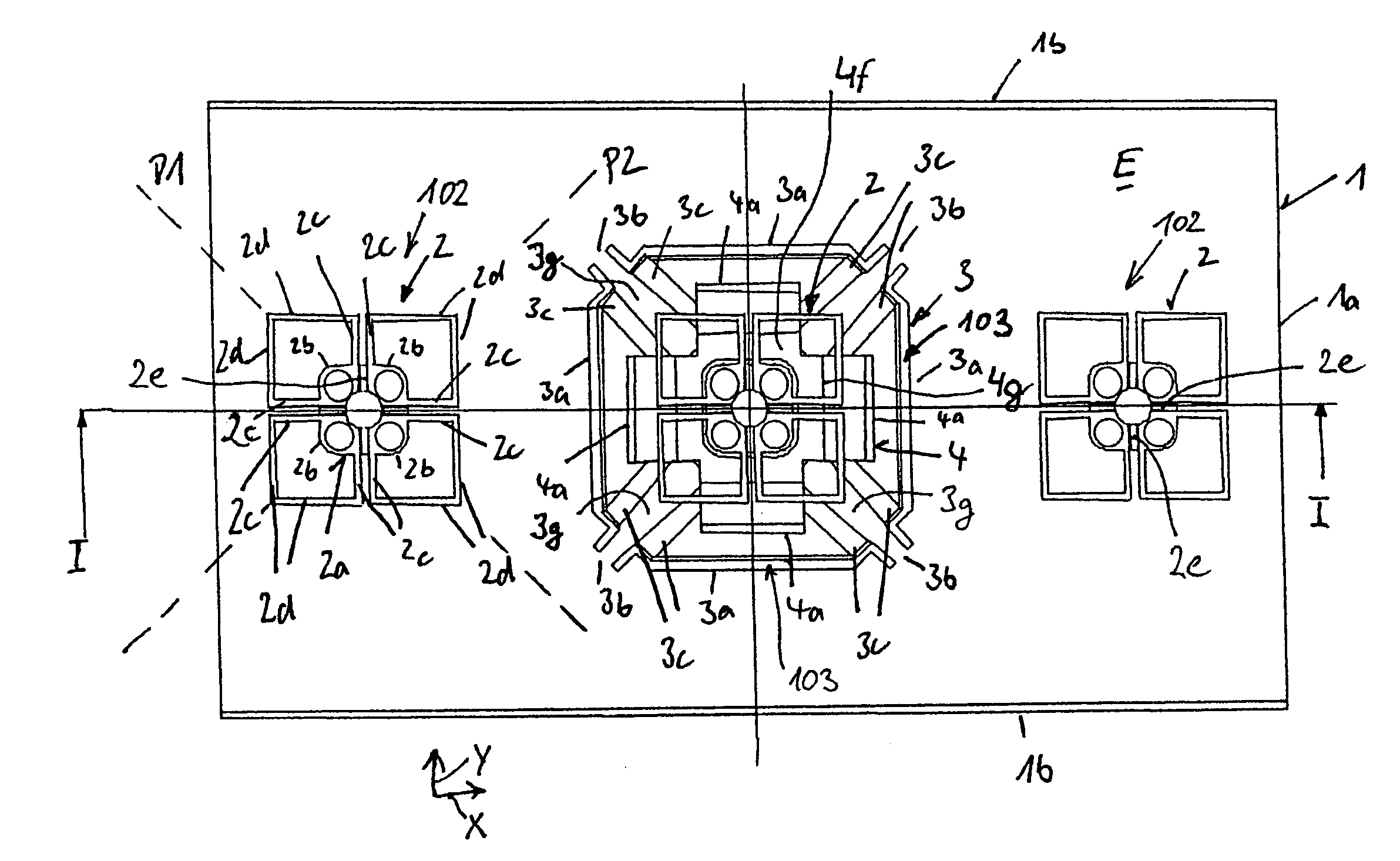
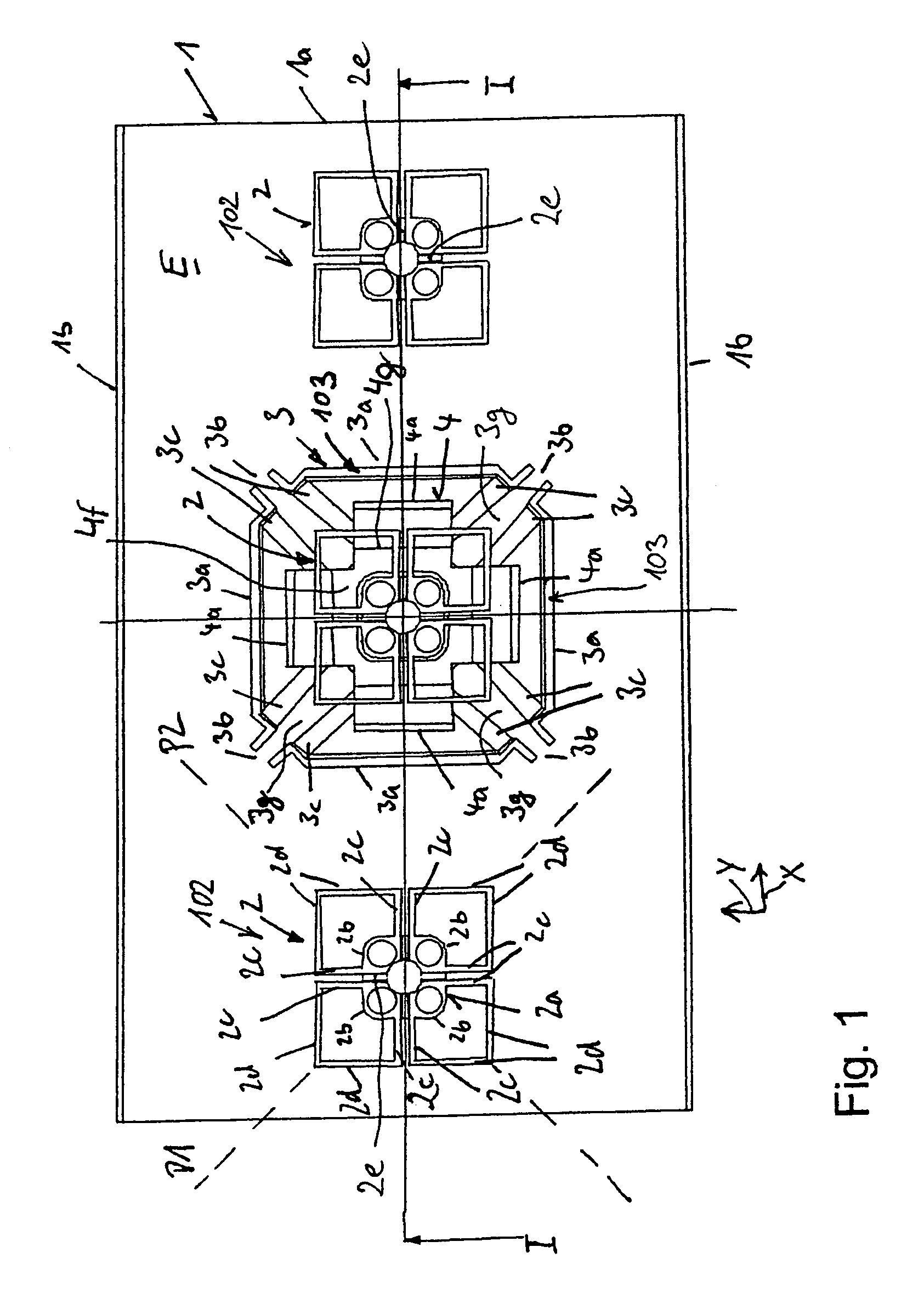
[0049]FIG. 4 shows a plan view of the antenna according to the invention. In the embodiment shown in FIG. 4, the same antenna elements 2 and 3 are used as in FIG. 1, and the antenna elements are also arranged in the same way as in the embodiment in FIG. 1, in a plan view. In contrast to the embodiment shown in FIG. 1, however, the left-hand and right-hand first antenna elements are also arranged on a platform, with this platform having a closed, essentially rectangular, platform surface 4c with a corresponding boundary 4d, which frames and surrounds the platform surface. The platform on which the central antenna element 2 is arranged also corresponds to the platform which is also used in the embodiment shown in FIG. 1.

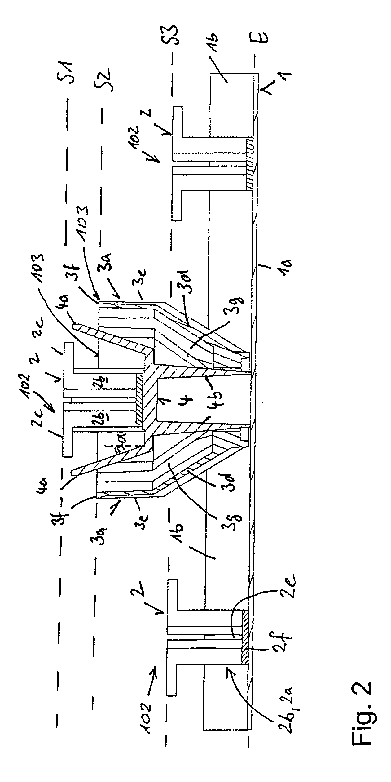
[0050]FIG. 5 shows a section view along the line II—II in FIG. 4. This shows in particular that the left-hand and right-hand platforms are identical, and have a different shape to the central platform. The left-hand and right-hand platforms essentially form a tower wit...

third embodiment

[0052]FIG. 7 shows a plan view of the antenna according to the invention. The antenna shown in FIG. 7 differs from the antenna shown in FIG. 1 by the use of a different type of second antenna element. Otherwise, the embodiment shown in FIG. 7 corresponds to the embodiment shown in FIG. 1, so that it will not be described in detail.

[0053]In FIG. 7, a dipole square 3′ is used instead of a cup-shaped antenna element 3, and has four dipoles which are in the form of rods and each comprise two dipole halves 3a′. The individual dipoles in this case run at an angle of 45° to the side walls 1b of the reflector 1. This means that, analogously to the cup-shaped antenna element in FIG. 1, the dipole square transmits and receives with the +45° polarization P1 and the −45° polarization P2. The design of antenna elements in the form of dipole squares is well known from the prior art. By way of example, reference is made to the document DE 198 23 749 A1, with this reference including its entire dis...


PUM


Abstract

An antenna, in particular a mobile radio antenna, operates in at least two frequency bands. Two or more dipole antenna elements are provided and are arranged in front of a reflector, which transmit and receive in two different frequency bands. The distance between the antenna element structure, the antenna elements or the antenna element top of at least one dipole antenna element for the higher frequency band is at a distance from the reflector plane which corresponds to at least 75% and at most 150% of the distance between an antenna element structure. An antenna element or an antenna element top of at least one dipole antenna element for the lower frequency band and the reflector plane, and/or the distance between the antenna element structure, the antenna elements or the antenna element top of at least one dipole antenna element for the higher frequency band is at a distance from the reflector plane which is greater than 0.4λ and is preferably less than 2λ with respect to the mid-frequency of the antenna element for the higher frequency.

Description

TECHNICAL FIELD OF THE INVENTION[0001]The invention relates to an antenna, in particular a mobile radio antenna, for operation in at least two frequency bands.BACKGROUND OF THE INVENTION[0002]Multiband antennas which allow reception and transmission of radiation in at least two different frequency ranges are known from the prior art. By way of example, the document DE 198 23 749 A1 discloses a dual-polarized multiband antenna which has first and second antenna elements. The first and second antenna elements transmit and receive in different frequency ranges and comprise dual-polarized dipole antenna elements which are arranged on a reflector and transmit and receive in polarizations which are aligned at +45° and −45° to the vertical. In the case of the multiband antenna which is disclosed in this document, the first antenna elements are in the form of cruciform dipoles which transmit and receive in an upper frequency band. The antenna elements in the lower frequency band are dipole ...

Claims


Application Information

Patent Timeline
Patent Type & Authority Patents(United States)
IPC IPC(8): H01Q21/26H01Q21/00
CPCH01Q1/246H01Q21/08H01Q5/42H01Q21/29H01Q21/26
Inventor GOTTL, MAXIMILIANHUBNER, MAGNUSMICHEEL, FELIXBOSS, MICHAEL
Owner TELEFON AB LM ERICSSON (PUBL)
Why Eureka
Try Eureka