
Electric double layer capacitor, electrolyte battery and method for manufacturing the same

a technology of double layer capacitors and electrolyte batteries, which is applied in the direction of cell components, final product manufacturing, sustainable manufacturing/processing, etc., can solve the problems of drop in performance of electric double layer capacitors, and achieve the effects of reducing contact surface area, preventing leakage and moisture entry, and increasing adhesiveness

Inactive Publication Date: 2006-07-18
SANYO ELECTRIC CO LTD +1
View PDF12 Cites 4 Cited by
  • Summary
  • Abstract
  • Description
  • Claims
  • Application Information

AI Technical Summary

Benefits of technology

The patent describes a method for making an electric double layer capacitor by sealing a cell with a synthetic resin sealing member. The method includes steps of providing a slit in the collector electrodes, inserting the cell into the slit, and joining the case halves by abutting them and applying ultrasonic vibration. The technical effect of this method is to improve the performance and reliability of the electric double layer capacitor.

Problems solved by technology

Particularly in the case of non-aqueous electrolytes, entry of moisture from outside causes electrolysis inside the cell (2), leading to a drop in performance as an electric double layer capacitor.

Method used


Image

  • Electric double layer capacitor, electrolyte battery and method for manufacturing the same
  • Electric double layer capacitor, electrolyte battery and method for manufacturing the same
  • Electric double layer capacitor, electrolyte battery and method for manufacturing the same

Examples


first embodiment

for Aqueous and Non-Aqueous Electric Double Layer Capacitors

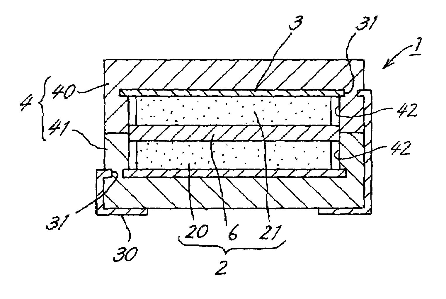
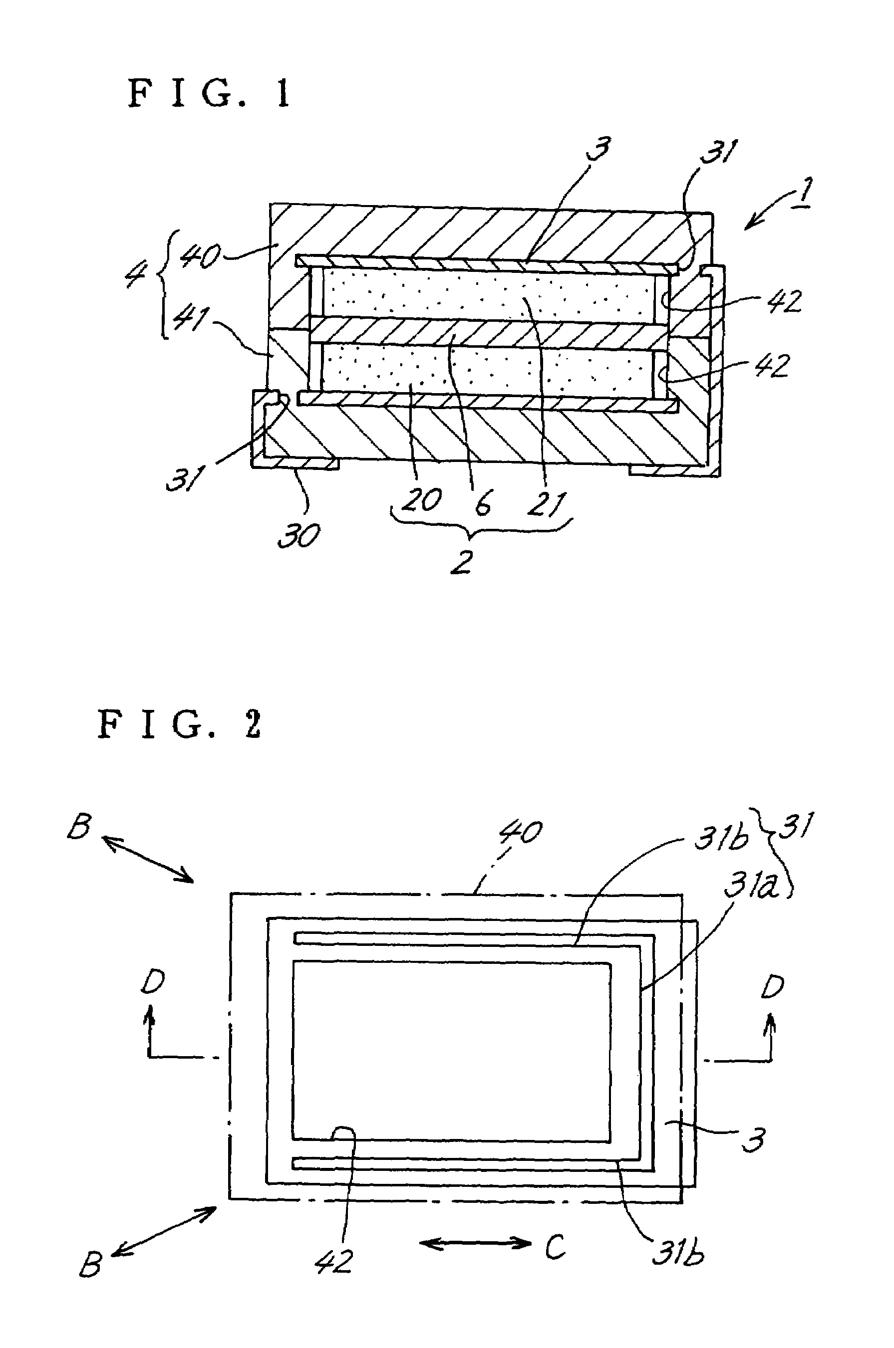
[0028]FIG. 1 is a cross-sectional view of an electric double layer capacitor (1) according to the present embodiment. A cell (2) is composed, in the conventional manner, of a pair of stacked polarizable electrodes (20) and (21), which sandwich a separator (6), with collector electrodes (3) and (30), made of stainless steel or the like, attached to outer sides of the polarizable electrodes (20) and (21). In the following description, the upper polarizable electrode (21) has a negative polarity, while the lower polarizable electrode (20) has a positive polarity. Needless to say, the negative and positive poles may be reversed.

[0029]A sealing member (4) is composed by arranging a parallelepiped first case half (40) and second case half (41), whose central portions are provided with recesses (42), vertically on top of one another so that the openings of their recesses (42) abut. The polarizable electrodes (20) and (21) and the ...

second embodiment

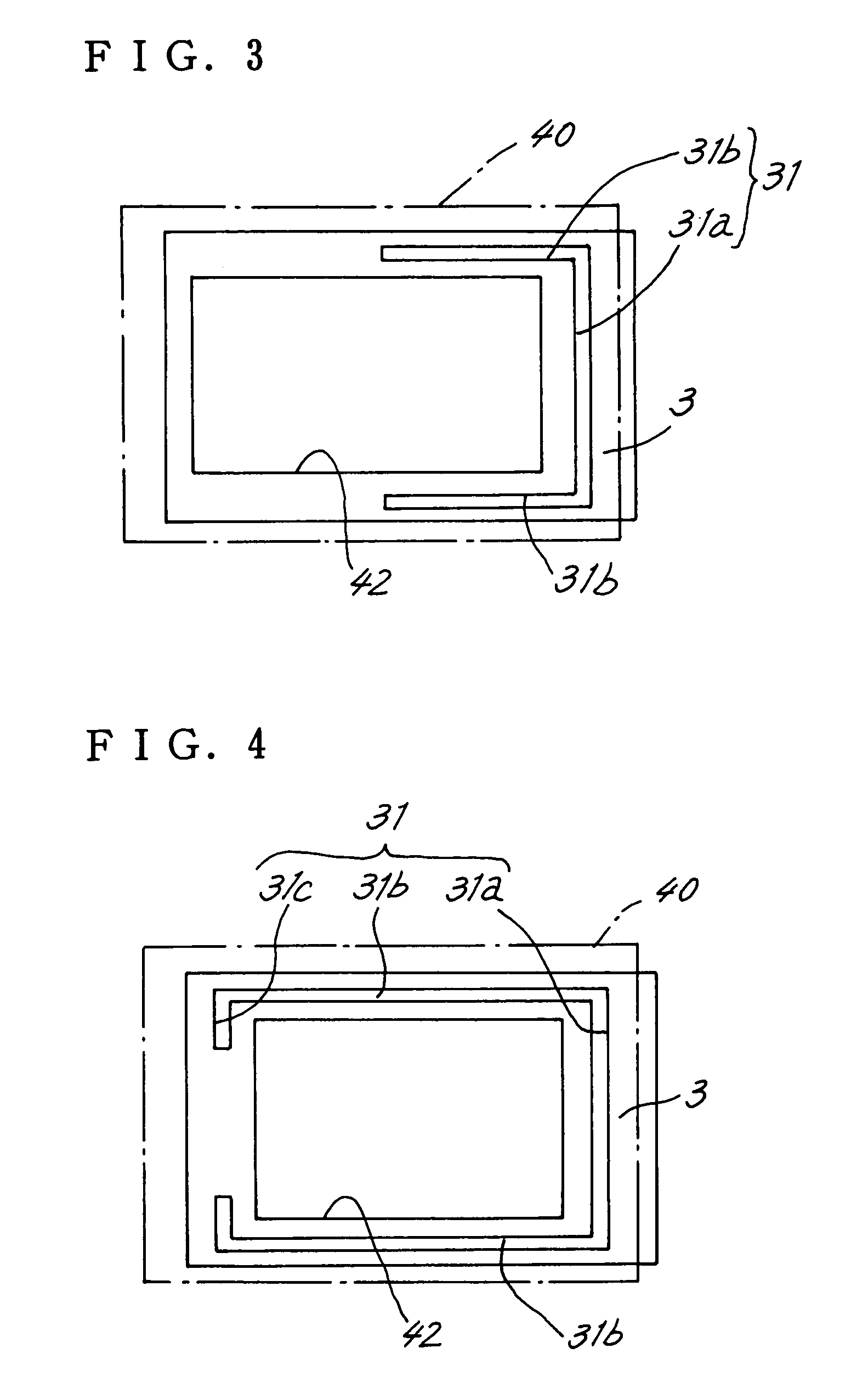
[0047]The configuration shown in FIG. 6 is also possible in order to effectively prevent leaking of electrolyte and entry of moisture from outside a cell (2). A plurality of slits (31) and (31) is provided substantially in parallel between a side surface of a first case half (40) and a recess (42), and each slit (31) extends along the side surface of the first case half (40).

[0048]Providing this plurality of slits (31) and (31) further increases the adhesiveness between the collector electrodes (3) and (30) and the first and second case halves (40) and (41). Accordingly, leaking of an electrolyte from a borderline L and entry of moisture from the borderline L are effectively prevented.

Electrolyte Battery

[0049]The present invention can also be applied to aqueous and non-aqueous electrolyte batteries.

[0050]An electrolyte battery differs from the electric double layer capacitor only in that some of the component materials are different, while the design and manufacturing method are sub...


PUM

PropertyMeasurementUnit
polarizableaaaaaaaaaa
charge-discharge behavioraaaaaaaaaa
dc voltageaaaaaaaaaa

Abstract

An electric double layer capacitor is provided with a cell, in which a pair of polarizable electrodes, which are impregnated with an electrolyte, are disposed in opposition on either side of a separator; wherein the polarizable electrodes are provided with collector electrodes, a peripheral portion of the cell is sealed by a sealing member composed of synthetic resin, and the sealing member is formed by abutting two case halves. A manufacturing method for the capacitor includes a process step of providing at least one long slit in the collector electrodes; a step of forming the case halves formed by insert molding on the collector electrodes and filling the slit, the case halves comprising a recess, one side of which extends in the lengthwise direction of the slit and, the cell being fitted into a portion inward from the slit; and a step of joining the case halves by abutting the case halves and applying ultrasonic vibration either in a perpendicular direction or a diagonal direction with respect to the lengthwise direction of the slit.

Description

BACKGROUND OF THE INVENTION[0001]1. Field of the Invention[0002]The present invention relates to an electric double layer capacitor, an electrolyte battery, and a method for manufacturing the same.[0003]2. Description of the Related Art[0004]Electric double layer capacitors are devices with excellent charge-discharge behavior.[0005]FIG. 7 is a cross-sectional view showing a cell (2) constituting a conventional electric double layer capacitor (1), as disclosed in JP 2001-351833A, for example. In it, a pair of polarizable electrodes (20) and (21) are stacked, sandwiching a separator (6), with metal collector electrodes (3) and (30) attached to outer sides of the polarizable electrodes (20) and (21). The polarizable electrodes (20) and (21) are composed by adding a conductive polymer, such as polypyrrole, to an active carbon that is in powder or fiber form, hardening this with a bonding material, and pressure forming. The polarizable electrodes (20) and (21) are impregnated with an ele...

Claims


Application Information

Patent Timeline
Patent Type & Authority Patents(United States)
IPC IPC(8): H01G9/00H01G9/10H01G11/00H01G11/66H01G11/70H01G11/78H01G11/80H01G11/82H01G11/84H01M2/02H01M2/08H01M10/04H01M10/05H01M10/0585H01M10/34
CPCH01G9/10H01G9/155H01M2/08H01M10/345H01M10/38Y10T29/49108Y02E60/124Y02E60/13Y10T29/417Y02E60/10Y02P70/50H01G11/80H01G11/84H01G11/82
Inventor TATEZONO, FUMIOOMURA, SEIJIITO, KIYOTAKAKOMATSU, TSUYOSHIHASHIMOTO, MAKOTO
Owner SANYO ELECTRIC CO LTD
Learn More