Time display system, method and device

a time display and time display technology, applied in the field of clocks, watches, electronic displays, can solve the problems of high numerical digit display, high design limitation, and high repetition and unattractiveness of numerical digit displays, and achieve the effect of enhancing the display effect of time, and enhancing the display

Inactive Publication Date: 2006-07-18
SEARCH & SOCIAL MEDIA PARTNERS
View PDF43 Cites 73 Cited by
  • Summary
  • Abstract
  • Description
  • Claims
  • Application Information

AI Technical Summary

Benefits of technology

[0047]Display of hour information. The present invention provides a system for displaying time of day information wherein color serves as a stand-alone, self-sufficient indicator of the current hour of the day, thereby altogether eliminating the need for an hour hand or hour digit. A different color is uniquely assigned to each of the twelve hours typically displayed by a traditional a

Problems solved by technology

While both of these time display methods can accurately and precisely convey time of day information to an observer, they are both limiting from a design perspective.
Incorporated into calculator watches, VCRs, mobile phones, and many other devices, numerical digit displays are highly,functional but almost as highly repetitive and unattractive.
As a result of these limitations, the time display function served by modern clocks and watches often clashes with the fashion and ornamental function.
Each of these offerings also suffers from its own inherent limitations.
The limitations typically fall into one of the following categories: (i) time is displayed accurately and precisely, but reading or learning to read the display is prohibitively difficult; (ii) time is displayed accurately, but unacceptably imprecisely; (iii) time is displayed in the traditional analog or digital method, but “a twist” is added that makes for a difference without any apparent advantage.
However, as the inventor admits in the disclosure itself, the time display method disclosed therein requires a “time-consuming data extraction process.” The same criticism can be leveled at other alternative methods in this category, such as Cordova, U.S. Pat. No. 5,526,327 (providing a time display method and device in which container-like areas fill over time to indicate the passing of hours, minutes and seconds) and Lyon, U

Method used


Image

  • Time display system, method and device
  • Time display system, method and device
  • Time display system, method and device

Examples


embodiment 30

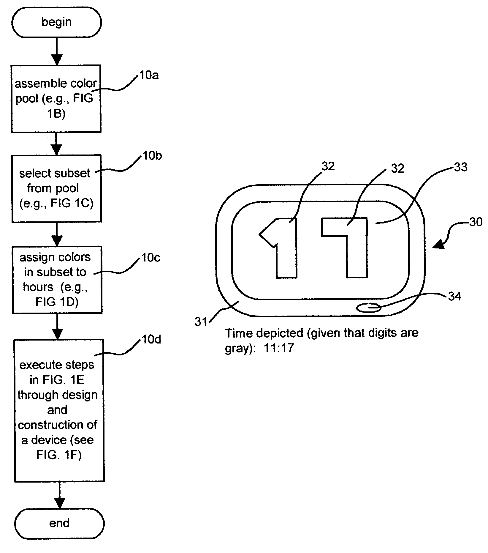
[0160]This particular hybrid embodiment 30 enjoys an inherent advantage over devices that display the time in conventional digital format: as depicted in FIG. 3A, the device 30 conveys both minute and hour information using only two numerical digits. Conventional digital format, however, requires four numerical-digits and a colon character, five symbols in all as depicted in FIG. 3B. Thus, holding the size of the electronic display constant, the two digits required in the time display mode depicted in FIG. 3A can be displayed at a greater size than the five symbols required in the time display mode depicted in FIG. 3B, and can therefore be read at greater distances. Moreover, color is demonstrably easier to discern from a distance than is an individual alphanumeric character.

[0161]The hybrid embodiment need not rely upon a flat-panel display. FIG. 4 depicts a color dial 40 with a multicolored surface; specifically, on the surface of this dial 40, twelve color segments 41 appear, eac...

embodiment 360

[0248]The same basic mechanisms depicted above can be combined in a TDD that indicates the current zodiac month rather than the current calendar month. A color-to-month matrix 370 in which colors are assigned to zodiac months appears in FIG. 37. A rotating color dial embodying the color sequence of this color-to-month matrix 370 turns intermittently once per month at the top of the month, as in the previous embodiment 360, except that the top of the month is defined by the zodiac calendar, the pertinent dates of which are listed in FIG. 37. Thus, referring to FIG. 38, if the black color segment of a rotating color dial 385 is visible through the aperture 383 in the clock face 384, then the current month, according to the zodiac calendar, is Aries.

Section 8: Using Environmental Sensors to Toggle between Display Modes

[0249]Rather than require the user to manually switch the TDD from one display mode to another as per the process depicted in FIG. 3D, an environmental sensor can be incl...


PUM


Abstract

A time display device (“TDD”)—equally adaptable to watches, clocks, computers, phones, and vehicles—indicates the current hour of the day by displaying a color that refers an observer to the disclosed color-to-hour matrix, thereby eliminating the traditional hour hand or digit altogether. Alternately adaptable to months, the system may be used with both mechanical and electronic displays. Various disclosed minute indicators provide minute indication by shape, complexity, company logo, air bubbles, or other novel methods. Environmental sensors allow switching between functions. TDD appearance is user-customizable via Internet. Birthstones, gemstones, and precious metals are alternately used as stand-alone time indicators.

Description

CROSS-REFERENCE TO RELATED APPLICATIONS[0001]Priority filing of U.S. provisional patent application No. 60 / 395,367, filed Jul. 12, 2002, and U.S. provisional patent application No. 60 / 372,974, filed Apr. 16, 2002, is claimed.STATEMENT REGARDING FEDERALLY SPONSORED RESEARCH AND DEVELOPMENT[0002]None.Reference to Sequence Listing, A Table, or A Computer Program Listing Appendix[0003]None.BACKGROUND OF THE INVENTION[0004]A portion of the disclosure of this patent document contains material which is subject to copyright protection. The copyright owner has no objection to the facsimile reproduction by anyone of the patent documents or patent disclosure, as it appears in the Patent and Trademark Office patent file or records, but otherwise reserves all rights whatsoever.[0005]1. Field of the Invention[0006]The present invention relates to clocks, watches, and electronic displays.[0007]2. Description of Related Arta. The Need for an Alternative Time Display Method[0008]Clocks and watches s...

Claims


Application Information

Patent Timeline
IPC IPC(8): G04C19/00G04B19/00G04B25/00G04B47/00G04C17/00G04G9/02G04G9/06G10H1/00
CPCG04B25/00G04C17/00G04C17/0091G04G9/0082G04G9/02G04G9/06G10H1/0083G04G9/124G10H2240/311G10H2230/015G10H2240/115G10H2240/285G10H2240/305
Inventor HARRISON, SHELTON E.
Owner SEARCH & SOCIAL MEDIA PARTNERS
Why Eureka
Try Eureka