Method and apparatus for power control in an ultra wideband impulse radio system

a radio system and impulse technology, applied in power management, transmission monitoring, wireless commuication services, etc., can solve problems such as interference between transmissions, and achieve the effects of reducing interference, reducing total power consumption, and being more energy efficien

Inactive Publication Date: 2006-07-18
ALEREON
View PDF4 Cites 117 Cited by
  • Summary
  • Abstract
  • Description
  • Claims
  • Application Information

AI Technical Summary

Benefits of technology

[0018]An advantage of the current invention is that interference is reduced. This is particularly important where multiple impulse radios are operating in close proximity (e.g., a densely utilized network), and their transmissions interfere with one another. Reducing the transmitter power of each radio to a level that produces satisfactory reception increases the total number of radios that can operate in an area without excess interference.
[0019]Another advantage of the current invention is that impulse radios can be more energy efficient. Reducing transmitter power to only the level required to produce satisfactory reception allows a reduction in the total power consumed by the transceiver, and thereby increases its efficiency.

Problems solved by technology

This is particularly important where multiple impulse radios are operating in close proximity (e.g., a densely utilized network), and their transmissions interfere with one another.

Method used


Image

  • Method and apparatus for power control in an ultra wideband impulse radio system
  • Method and apparatus for power control in an ultra wideband impulse radio system
  • Method and apparatus for power control in an ultra wideband impulse radio system

Examples


first embodiment

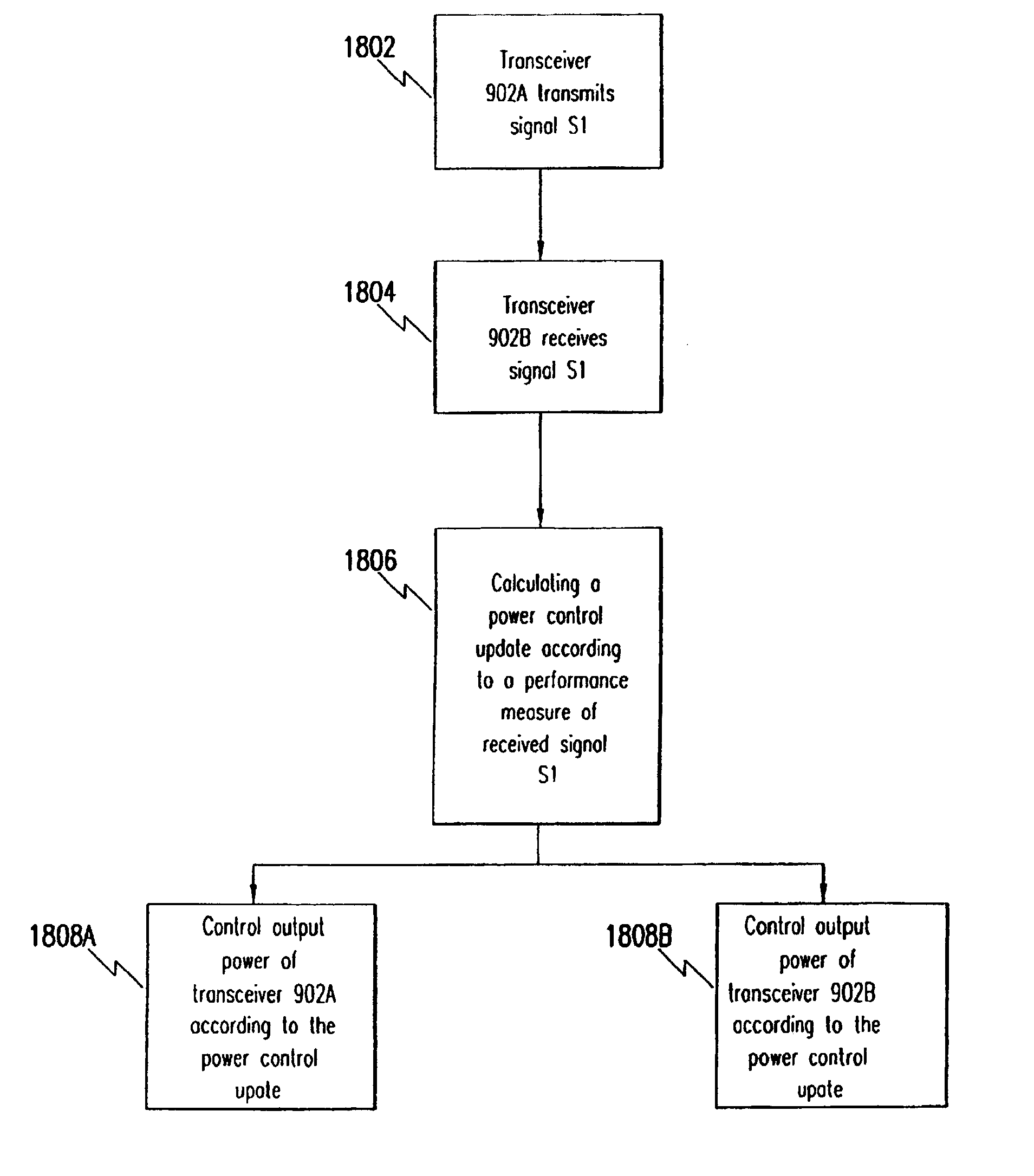
[0199]In a first embodiment, the signal strength of the received signal is used as a performance measurement. The power control update, dP, is given by:

dP=K(Pref−PS1)[0200]where K is a gain constant;[0201]PS1 is the signal strength of received signal S1;[0202]Pref is a signal strength reference; and[0203]dP is the power control update (which is preferable in the unit of Volts).

[0204]The output level of transmitter 602A (of transceiver 902A) is therefore increased when PS1 fills below Pref, and decreased when PS1 rises above Pref. The magnitude of the update is linearly proportional to the difference between these two signals. Note that the power control update can be equivalently expressed as an absolute rather than a differential value. This can be achieved by accumulating the differential values dP and communicating the resulting output level P as follows:

Pn=Pn−1+dP,[0205]Where Pn is the output level (e.g., voltage level or power level) to be transmitted during the next evaluation...

second embodiment

[0217]In a second embodiment, the SNR of the received signal is used as a performance measurement. The power control update, dP, is given by:

dP=K(SNRref−SNRS1)[0218]where K is a gain constant;[0219]SNRS1 is the signal-to-noise ratio of received signal S1; and[0220]SNRref is a signal-to-noise ratio reference.

[0221]The power of transmitter 602A (of transceiver 902A) is therefore increased when SNRS1 falls below SNRref and decreased when SNRS1 rises above SNRref. The magnitude of the update is linearly proportional to the difference between these two signals. Note that the power control update can be equivalently expressed as an absolute rather than a differential value. As described above, those skilled in the art will recognize that many alternative equivalent formulations are possible for calculating a power control update according to received signal SNR.

[0222]A control loop diagram illustrating the functionality of this embodiment will now be described with reference to FIG. 21. A...

third embodiment

[0225]In a third embodiment, the BER of the received signal is used as a performance measurement. The power control update, dP, is given by:

dP=K(BERS1−BERref)[0226]where K is a gain constant;[0227]BERS1 is the bit error rate of received signal S1; and[0228]BERref is a bit error rate reference.

[0229]Note that the sign is reversed in this case because the performance indicator, BER is reverse sensed, i.e. a high BER implies a weak signal. The power of transmitter 602A (of transceiver 902A) is therefore decreased when BERS1 falls below BERref, and increased when BERS1 rises above BERref. The magnitude of the update is linearly proportional to the difference between these two signals. Note that the power control update can be equivalently expressed as an absolute rather than a differential value. As described above, many alterative formulations are possible for calculating a power control update according to received signal BER.

[0230]Note that BER measurements span a large dynamic range...


PUM


Abstract

A method for power control in an ultra wideband impulse radio system includes: (a) transmitting an impulse radio signal from a first transceiver; (b) receiving the impulse radio signal at a second transceiver; (c) determining at least one performance measurement of the received impulse radio signal; and (d) controlling output power of at least one of the first transceiver and the second transceiver in accordance with the at least one performance measurement.

Description

[0001]This is a continuation of U.S. application Ser. No. 09 / 586,163, filed Jun. 2, 2000, now U.S. Pat. No. 6,571,089, which is a continuation-in-part of U.S. application Ser. No. 09 / 332,501, filed Jun. 14, 1999, which issued as U.S. Pat. No. 6,539,213 on Mar. 25, 2003.BACKGROUND OF THE INVENTION[0002]1. Field of the Invention[0003]The present invention generally relates to wireless communications, and more specifically, to a system and a method for impulse radio power control.[0004]2. Related Art[0005]Recent advances in communications technology have enabled an emerging, revolutionary ultra wideband technology (UWB) called impulse radio communications systems (hereinafter called impulse radio).[0006]Impulse radio was first fully described in a series of patents. Including U.S. Pat. No. 4,641,317 (issued Feb. 3, 1987), U.S. Pat. No. 4,813,057 (issued Mar. 14, 1989) U.S. Pat. No. 4,979,186 (issued Dec. 18, 1990) and U.S. Pat. No. 5,363,108 (issued Nov. 8, 1994) to Larry W. Fullerton....

Claims


Application Information

Patent Timeline
Patent Type & Authority Patents(United States)
IPC IPC(8): H04Q7/20H04B1/69H04B1/7163H04B1/7183H04B7/005H04W52/20H04W52/24H04W52/36
CPCH04B1/7163H04W52/20H04W52/241H04W52/362H04W52/367H04W52/24H04B1/7183H04B2001/6908Y02B60/50
Inventor RICHARDS, JAMES L.FULLERTON, LARRY W.COWIE, IVAN A.
Owner ALEREON
Why Eureka
Try Eureka