Circuit apparatus and method for testing integrated circuits using weighted pseudo-random test patterns

a technology of integrated circuits and test patterns, applied in error detection/correction, instruments, solid-state devices, etc., can solve problems such as the difficulty of verifying the functionality of each logic gate, the inability to test the functionality and the fault of at least one logic ga

Active Publication Date: 2006-07-18
TOSHIBA AMERICA ELECTRONICS COMPONENTS +2
View PDF7 Cites 2 Cited by
  • Summary
  • Abstract
  • Description
  • Claims
  • Application Information

AI Technical Summary

Benefits of technology

[0015]FIG. 3 is a block diagram of a circuit configuration included in a conventional programmable weighted random pattern generator; and

Problems solved by technology

Verifying the functionality of each logic gate can be difficult because of the limited number of input / output (I / O) pins for the integrated circuit and the complex interconnections between the inputs and outputs of the multitude of logic gates.
When the output data patterns do not match predicted output data patterns, it is known that a fault has occurred in at least one of the logic gates.
However, such a test process may require extremely long test times due to the need for generating and inputting a large number of different input data patterns.
However, one problem associated with applying random data patterns is that only a portion of the logic circuits will be tested, and therefore, there is a likelihood that an integrated circuit having a defect may go undetected.
However, the increased number of input data patterns lengthens the overall test time, and thus, increases the overall manufacturing cost for the integrated circuit.
Many integrated circuits include logic gate structures that are difficult to test using a purely random input data pattern.

Method used


Image

  • Circuit apparatus and method for testing integrated circuits using weighted pseudo-random test patterns
  • Circuit apparatus and method for testing integrated circuits using weighted pseudo-random test patterns
  • Circuit apparatus and method for testing integrated circuits using weighted pseudo-random test patterns

Examples


Embodiment Construction

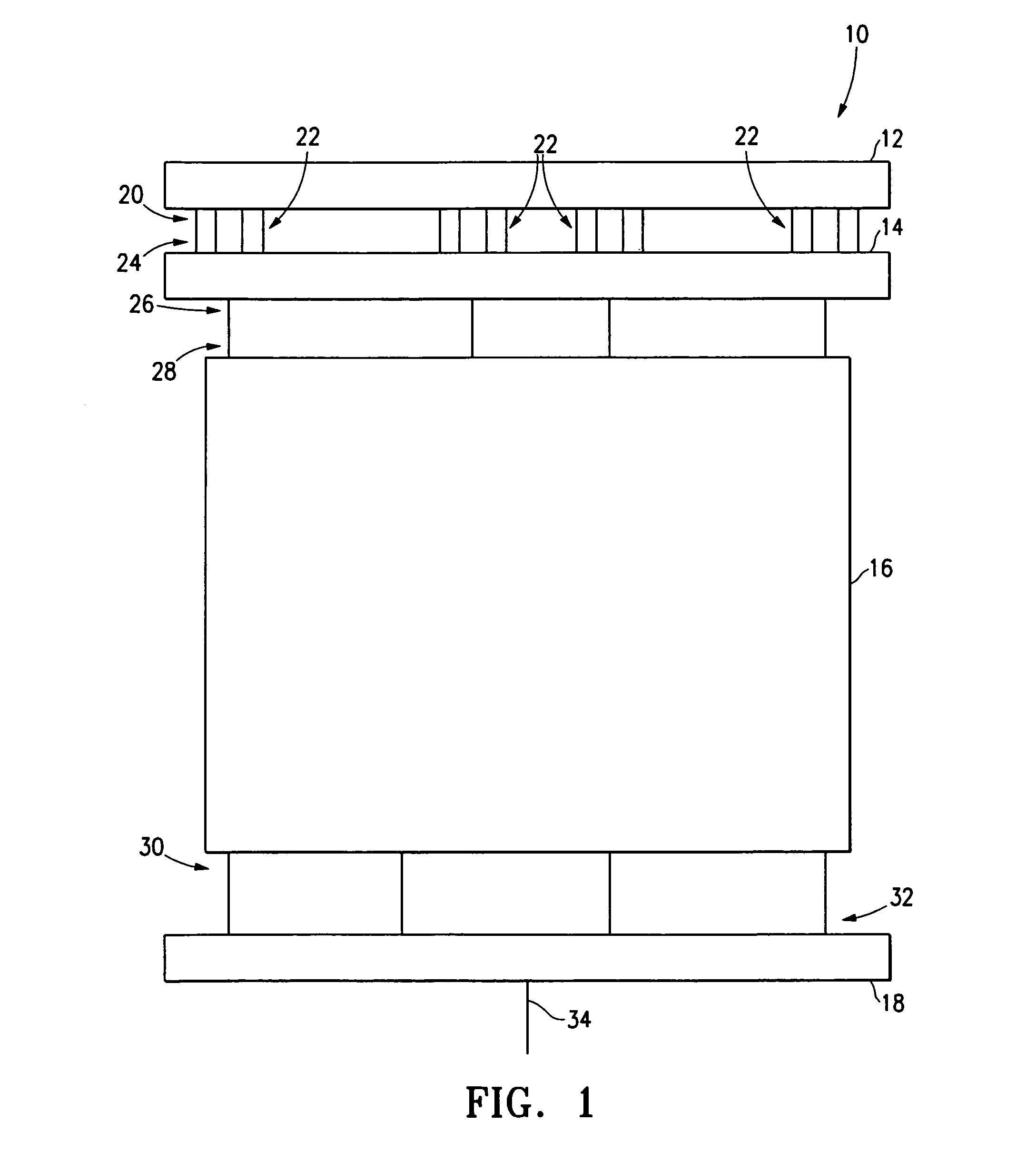
[0017]FIG. 1 is a block diagram of a typical logic built-in self test (“LBIST”) test configuration 10 which utilizes a psuedo-random pattern generation technique. The LBIST test configuration is also referred to as a scan-path structure called a self test using MSIR and parallel shift register sequence generator (“STUMPS”). The STUMPS structure is a built-in architecture for testing multiple chip systems at high throughput speeds. The LBIST test configuration includes a linear feedback shift register (“LFSR”) 12, programmable weighted random pattern generator (“PWR”) 14, integrated circuit to be tested 16, and multiple input shift register (“MISR”) 18. The LFSR as sixteen outputs 20, comprised of four groups of four outputs 22, that are coupled to sixteen corresponding inputs 24 of the PWR. The PWR has four outputs 26 that are coupled to four corresponding inputs 28 of the integrated circuit. The integrated circuit has four outputs 30 that are coupled to four corresponding inputs 32...


PUM


Abstract

A method for testing an electronic circuit includes selecting an input signal using a first multiplexer, selecting a signal to be input to the first multiplexer using at least one other multiplexer, and controlling the at least one other multiplexer using a selection signal output from a control circuit.

Description

FIELD OF THE INVENTION[0001]The present invention relates to testing of integrated electronic circuits, and in particular, to built-in self test circuits and methods for testing the functionality of integrated electronic circuits.BACKGROUND OF THE INVENTION[0002]A single very large scale integration (VLSI) semiconductor chip may contain thousands of interconnected logic gates which may include, for example, AND, OR, NAND, NOR, and XOR gates. A critical part of the manufacturing process for any such integrated circuit is verifying the functionality of the logic gates included in the integrated circuit. Verifying the functionality of each logic gate can be difficult because of the limited number of input / output (I / O) pins for the integrated circuit and the complex interconnections between the inputs and outputs of the multitude of logic gates. In many cases, multiple channels within the integrated circuit share I / O pins.[0003]During functional tests of an integrated circuit contained ...

Claims


Application Information

Patent Timeline
Patent Type & Authority Patents(United States)
IPC IPC(8): G01R31/28G01R31/3185H01L21/822H01L27/04
CPCG01R31/318385G01R31/318566G01R31/318547
Inventor KIRYU, NAOKIBUSHARD, LOUIS B
Owner TOSHIBA AMERICA ELECTRONICS COMPONENTS
Why Eureka
Try Eureka