High frequency dynamics resonator assembly

a high frequency dynamic and resonator technology, applied in the field of resonators, can solve the problems of affecting the performance of the combustor, exposing the resonator to a heavily non-uniform flow and pressure environment, and destroying the hardware of the combustor quickly

Active Publication Date: 2006-07-25
SIEMENS ENERGY INC
View PDF14 Cites 74 Cited by
  • Summary
  • Abstract
  • Description
  • Claims
  • Application Information

AI Technical Summary

Benefits of technology

[0011]The scoop has a top plate and at least one side wall extending substantially perpendicularly therefrom. The top plate of the scoop can include at least one opening. The at least one side wall of the scoop is attached to the resonator such that the scoop is disposed above the resonator plate and such that the top plate substantially overhangs the plate. The at least one side wall of the scoop can be attached to the resonator by one of welding or brazing. Further, the scoop includes one side without a side wall so as to provide an opening into a space defined between the scoop and the resonator plate. In use, the scoop can capture a passing fluid so as to substantially equalize the pressure impinging on the resonator plate.

Problems solved by technology

Without a damping device, such frequencies can quickly destroy combustor hardware.
However, if the actual conditions vary from the assumed conditions, the resonator may not perform as designed, which in turn can detrimentally affect the performance of the combustor.
The operating environment of a turbine engine can expose resonators to heavily non-uniform flow and pressure environments.
For example, the air flow entering the combustor section is non-uniform, and when this non-uniform flow is combined with the irregular geometries of the neighboring components, a complex flow pressure field develops.
Further, the resonators themselves can restrict flow depending on their size.
Such restriction can accelerate the flow and diminish the static pressure over the resonators, which typically changes the pressure drop from the design assumption.
Moreover, if such non-uniformities must be accounted for in the design, the design of the resonator can become significantly complicated.

Method used


Image

  • High frequency dynamics resonator assembly
  • High frequency dynamics resonator assembly
  • High frequency dynamics resonator assembly

Examples


Embodiment Construction

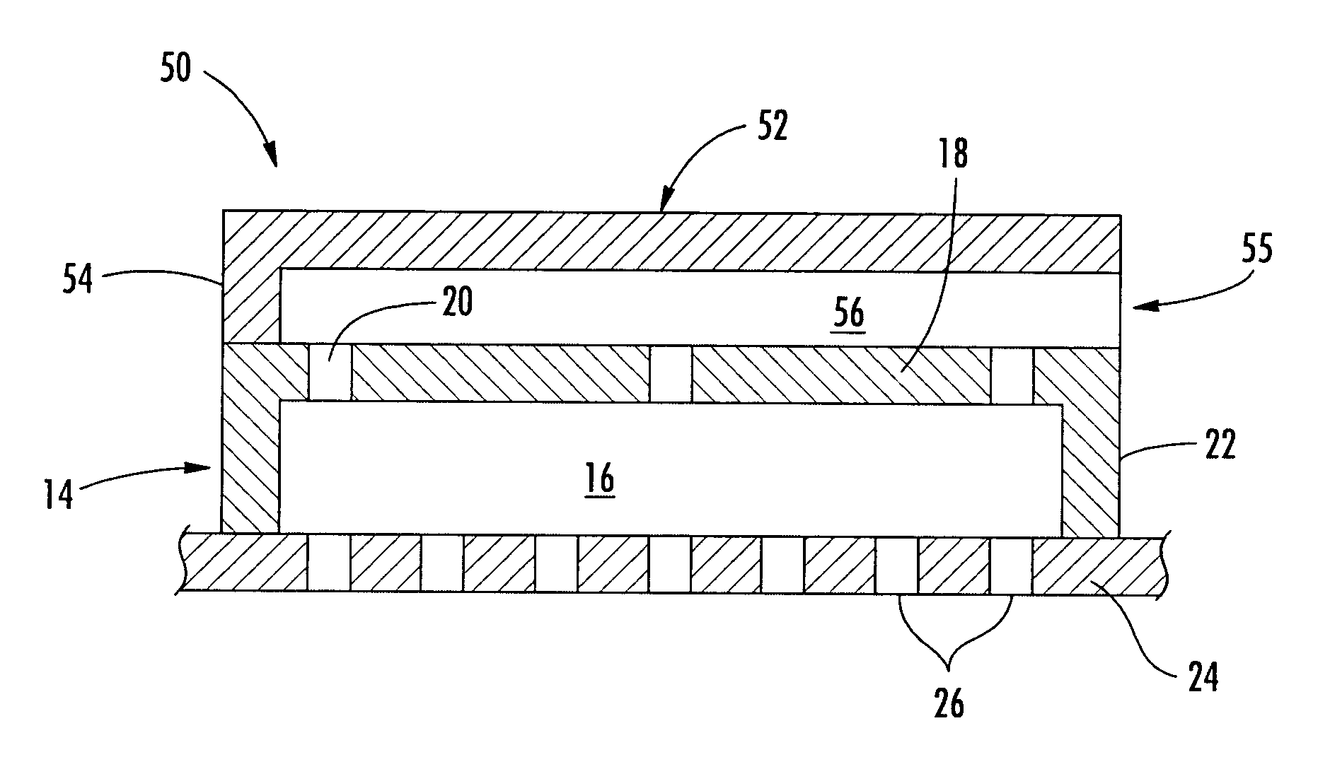
[0030]Aspects of the present invention address the shortcomings of prior resonator designs, particularly when such resonators are placed in non-uniform flow and pressure environments. Aspects of the present invention relate to resonators including one or more features for delivering a more predictable pressure field to the resonator and / or for more evenly distributing the pressure prior to impinging on the resonator. Such features can include a flow scoop or another box volume. Aspects of the present invention can help to bring the actual conditions experienced by the resonator more in line with assumed design considerations.

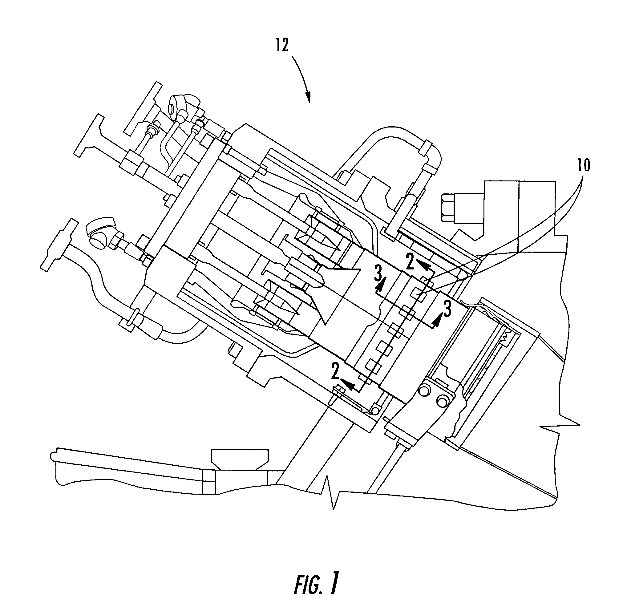
[0031]Embodiments of the invention will be explained in the context of a resonator for a turbine engine. Embodiments of the invention are shown in FIGS. 6–8, but the present invention is not limited to the illustrated structure or application. For example, the resonator configurations according to the present invention can be used an any section of the engine th...


PUM


Abstract

Aspects of the invention relate to resonator assemblies for use in non-uniform flow environments. The resonator assemblies include one or more features, such as a box or a scoop, for substantially equalizing the pressure on the resonator. In the box configuration, a box is attached on top of the resonator. The box has a top plate with a plurality of openings and at least one side wall extending from the entire periphery of the top plate. A plenum is defined between the box and the resonator plate. In the scoop configuration, a scoop is attached to the top of the resonator such that the scoop substantially overhangs the resonator. The scoop includes at least one side wall extending substantially perpendicularly therefrom, except for one side without a side wall so as to provide an opening into a space defined between the scoop and the resonator.

Description

FIELD OF THE INVENTION[0001]The invention relates in general to turbine engines and, more particularly, to resonators for suppressing acoustic energy in a turbine engine.BACKGROUND OF THE INVENTION[0002]Various damping devices can be used in connection with turbine engines to suppress certain undesired frequencies of dynamics including the frequency band known as screech (1000–5000 Hz). Such high frequency dynamics can result from, for example, burning rate fluctuations inside the combustor section of the turbine. Without a damping device, such frequencies can quickly destroy combustor hardware. Thus, one or more damping devices 10 can be associated with the combustor section 12 of a turbine engine, as shown in FIG. 1. One commonly used damping device 10 is a resonator.[0003]FIGS. 2–5 show one example of a resonator 14 known as a Helmholtz resonator. Generally, the resonator 14 provides a closed cavity 16 defined by a plate 18 having a plurality of inlet openings 20 therein and at l...

Claims


Application Information

Patent Timeline
Patent Type & Authority Patents(United States)
IPC IPC(8): F02C7/24F23M20/00
CPCF23M20/005F05B2260/96F23R2900/00014
Inventor BLAND, ROBERTRYAN, WILLIAM
Owner SIEMENS ENERGY INC
Why Eureka
Try Eureka