Visual documentation of micro-cracks during tensile coupon testing

a technology of tensile coupon and micro-cracks, applied in the field of composite materials and tensile coupon testing, can solve the problems of time-dependent micro-structural damage of many fiber-reinforced composite materials, reduced stiffness, and more serious damag

Active Publication Date: 2006-07-25
THE BOEING CO
View PDF16 Cites 11 Cited by
  • Summary
  • Abstract
  • Description
  • Claims
  • Application Information

AI Technical Summary

Benefits of technology

[0012]In a further aspect of the present invention, a method for determination of criteria ensuring almost unlimited fatigue life of carbon-reinforced composite structures comprises the steps of: providing a test unit including a lower test grip, an upper test grip, a stereomicroscope having a digital camera attached, a microscope light, and a camera strobe light; providing a specimen made out of a carbon-reinforced composite material and having a strain gage attached; preparing an edge of the specimen for photo microscopy; inserting the specimen into the lower test grip and the upper test grip; illuminating the prepared edge with the microscope light and the camera strobe light; applying a first tensile load to the specimen using the lower test grip and the upper test grip; capturing a first image provided by the stereomicroscope with the digital camera; measuring strain with the strain gage at the first tensile load; recording a first x-y plot showing tensile strength vs. strain; pairing the first image with the first x-y plot; applying a second tensile load to the specimen using the lower test grip and the upper test grip; capturing a second image provided by the stereomicroscope with the digital camera; measuring strain with the strain gage at the second tensile load; recording a second x-y plot showing tensile strength vs. strain; pairing the first image with the second x-y plot; observing first occurrence of micro-cracks in the first image; observing growth of the micro-cracks in the second image; determining tensile stress of the first occurrence of the micro-cracks; and providing the determined tensile stress to aerospace industry for avoiding fatigue failures of a carbon-reinforced composite structure manufactured out of said carbon reinforced composite material.

Problems solved by technology

Many fiber-reinforced composite materials experience time-dependent micro-structural damage at loads far below their failure stress.
Damage here refers to ply-level micro-structural changes such as matrix cracking and fiber—matrix debonding.
Such micro-cracking can have significant softening effect in the off-axis fiber directions and may cause more serious forms of damage, such as transverse cracking, delamination, and finally fiber failure.
As the load on fiber-reinforced composite materials increases, the effective stiffness may be reduced and an onset-of-damage may be observed which is caused by internal micro-cracks in the resin.
The fatigue life capability of a composite material and, therefore, the capability to withstand repeated loading, are expected to be limited by the onset-of-damage, the micro-cracking.
Such method has been described, for example, by Scott T. Burr, David L. Sikarskie in “Damage Characterization of Woven Composites Under Static Tensile Stress”, 1995 SEM Spring Conference and Exhibit, June 12–14, Grand Rapids, Mich., U.S.A. Despite the enormous time and test material expense, this method is not always successful since the micro-cracks may close when the load is released.
Furthermore, the cross section may not have been taken at the exact location where micro-cracks exist.
While the dynamic growth of a micro-crack can be monitored using the acoustic emission method, this method cannot reliably determine the initial formation of micro-cracks.

Method used


Image

  • Visual documentation of micro-cracks during tensile coupon testing
  • Visual documentation of micro-cracks during tensile coupon testing
  • Visual documentation of micro-cracks during tensile coupon testing

Examples


Embodiment Construction

[0027]The following detailed description is of the best currently contemplated modes of carrying out the invention. The description is not to be taken in a limiting sense, but is made merely for the purpose of illustrating the general principles of the invention, since the scope of the invention is best defined by the appended claims.

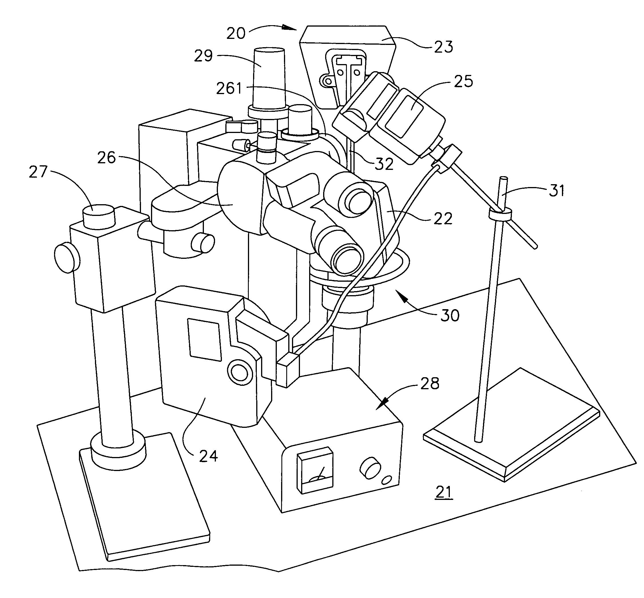
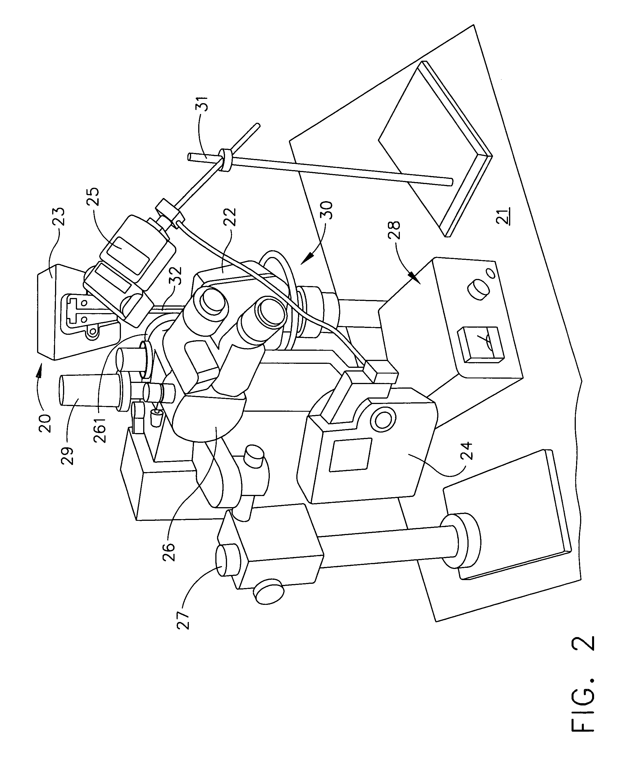
[0028]Broadly, an embodiment of the present invention provides a test method for visual documentation of the formation and growth of micro-cracks in carbon-reinforced composite materials during tensile coupon testing. Contrary to the known prior art, only one specimen is needed to obtain information about formation and growth of micro-cracks in carbon-reinforced composite materials where currently destructive testing of many specimens is required. Furthermore, the test method according to one embodiment of the present invention will allow visually following the initial formation as well as the growth of existing micro-cracks under an increasing tensile ...


PUM

PropertyMeasurementUnit
thicknessaaaaaaaaaa
widthaaaaaaaaaa
tensile coupon testingaaaaaaaaaa

Abstract

A test method for visual documentation of micro-cracks during tensile coupon testing includes the steps of: assembling a test unit; inserting a carbon-reinforced composite specimen having a prepared edge into the tensile coupon testing machine; illuminating the prepared edge of the specimen with a camera strobe light and a microscope light; applying a tensile load to the specimen; and capturing images (at 10% increments of the expected failing stress) of the prepared edge of the specimen with a digital camera that is attached to a stereomicroscope. Using the test method of the present invention photographic documentation of the formation and growth of micro-cracks in carbon-reinforced composite materials under tensile load is possible. The obtained data may be used to avoid or limit fatigue failure of carbon-reinforced structures used, for example, in the aerospace industry, for example, in spacecrafts and advanced military aircraft.

Description

BACKGROUND OF THE INVENTION[0001]The present invention generally relates to composite materials and tensile coupon testing and, more particularly, to carbon-reinforced composite materials and a test method for visual documentation of the formation and growth of micro-cracks in these materials during tensile coupon testing.[0002]The requirements for material used in the aerospace industry are manifold. Demands include improved toughness, lower weight, as well as increased resistance to fatigue and corrosion. The boundaries of material properties are being constantly extended as manufacturers strive to give the next generation of aircraft improved performance while making them more efficient. The use of fiber-reinforced composite materials over metals and their alloys over the past 20 years has increased significantly because of the weight savings and the improvement in fatigue life and corrosion control. Fiber-reinforced composite materials contain a strong and stiff fiber, such as a...

Claims


Application Information

Patent Timeline
Patent Type & Authority Patents(United States)
IPC IPC(8): G01L1/24
CPCG01N3/08G01N21/8806G01N19/08G01N2203/0647G01N2203/0062
Inventor BOHLMANN, RAYMOND E.HURD, MILTON D.
Owner THE BOEING CO
Why Eureka
Try Eureka