Safety fuel injection pump

a fuel injection pump and safety technology, applied in the direction of pump, positive displacement liquid engine, liquid fuel engine, etc., can solve the problems of poor lubrication (deterioration of lubricity) seizing of the plunger, and extraneous matters getting stuck among the operating members, so as to prevent the spread of damage and the damage of the housing

Active Publication Date: 2006-07-25
DENSO CORP
View PDF10 Cites 8 Cited by
  • Summary
  • Abstract
  • Description
  • Claims
  • Application Information

AI Technical Summary

Benefits of technology

[0013]It is therefore an object of the present invention to provide a safety fuel injection pump capable of preventing spread of damage when water or extraneous matters accidentally mixed into fuel cause defective operation of a plunger and the like.
[0015]In the above structure, the main shaft, which is rotated by the internal combustion engine, and the cam, which rotates integrally with the main shaft, are formed separately. The rotation of the cam is transmitted in the form of the reciprocation of the plunger. Further, the connecting portion for connecting the main shaft with the cam is formed. Since the strength of the connecting portion is set to a value lower than the damage strength of the housing, the main shaft and the cam can be separated from each other before the housing is damaged. If the connected state is eliminated and the main shaft and the cam are separated from each other, the main shaft freely turns in the cam. Therefore, even if the main shaft is driven by the internal combustion engine, the rotational movement of the main shaft is not transmitted to the cam, and the function of the fuel injection pump is stopped. As a result, the damage of the housing can be prevented and the spread of the damage can be prevented.

Problems solved by technology

However, there is a possibility that the extraneous matters get stuck among operating members such as the cam, the cam ring, the plunger, the suction valve and the discharge valve, which are disposed downstream of the fuel lubrication bypass passage and housed in the cam chamber or are disposed downstream of the suction quantity control electromagnetic valve for performing rotation movement, reciprocating movement and the like.
If water and the like are accidentally mixed into the fuel, there is a possibility that poor lubrication (deterioration of lubricity) occurs among the sliding members such as the plunger housed in the cam chamber.
The poor lubrication between the plunger and an inner peripheral surface of a plunger sliding hole can cause seizing of the plunger.
As a result, there is a possibility that an excessive thrust force is applied to the cam ring and the plunger is damaged.
If the extraneous matters get stuck at a seat portion of the operating member such as the suction valve or the discharge valve, fluid-tightness of a sealing portion cannot be ensured and an appropriate pressure-feeding quantity (a discharging quantity) of the fuel cannot be obtained.
In addition, high pressure of the continuously pressurized fuel is applied to the plunger.
If the high pressure of the fuel is continuously applied to the plunger, the poor lubrication can occur between the plunger and the inner peripheral surface of the plunger sliding hole and the seizing of the plunger can be caused.
In this case, there is a possibility that the excessive thrust force is applied to the cam ring and the plunger is damaged.
If the plunger is damaged, there is a possibility that fragments of the damaged plunger move through the cam chamber and get stuck into a clearance between the housing and the cam ring.
In this case, if the housing is made of aluminum, there is a possibility that the housing is damaged and the damage spreads.
Therefore, cost will be increased and mountability to a vehicle and the like will be deteriorated.
In the case where the fuel is stored in a metal drum and the like and is supplied from the metal drum to the vehicle, the water can be accidentally mixed into the fuel.
Therefore, there is a possibility that the fuel including a large amount of water is used in the fuel injection pump if the fuel is supplied from the metal drum.

Method used


Image

  • Safety fuel injection pump
  • Safety fuel injection pump
  • Safety fuel injection pump

Examples


first embodiment

[0024](First Embodiment)

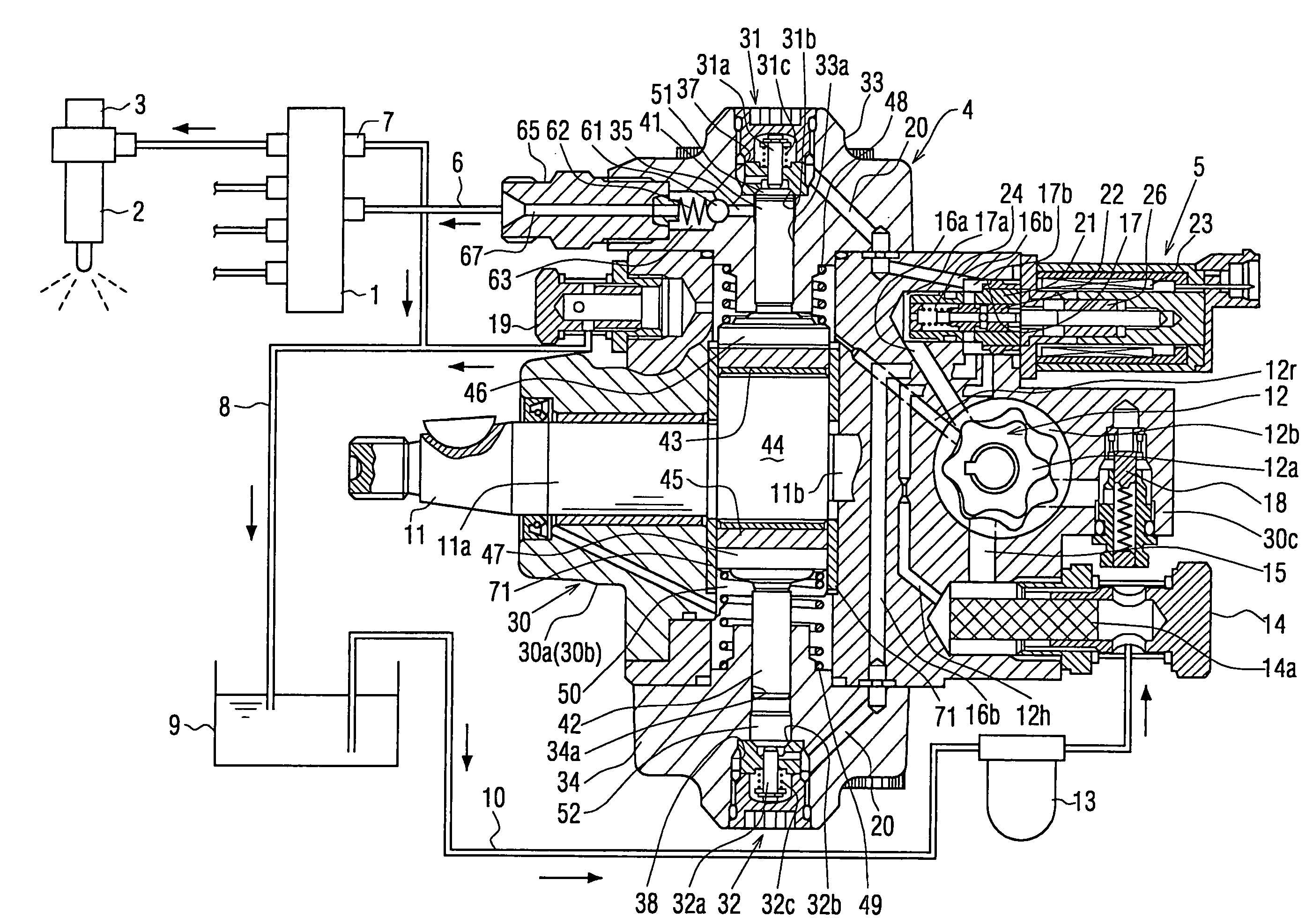
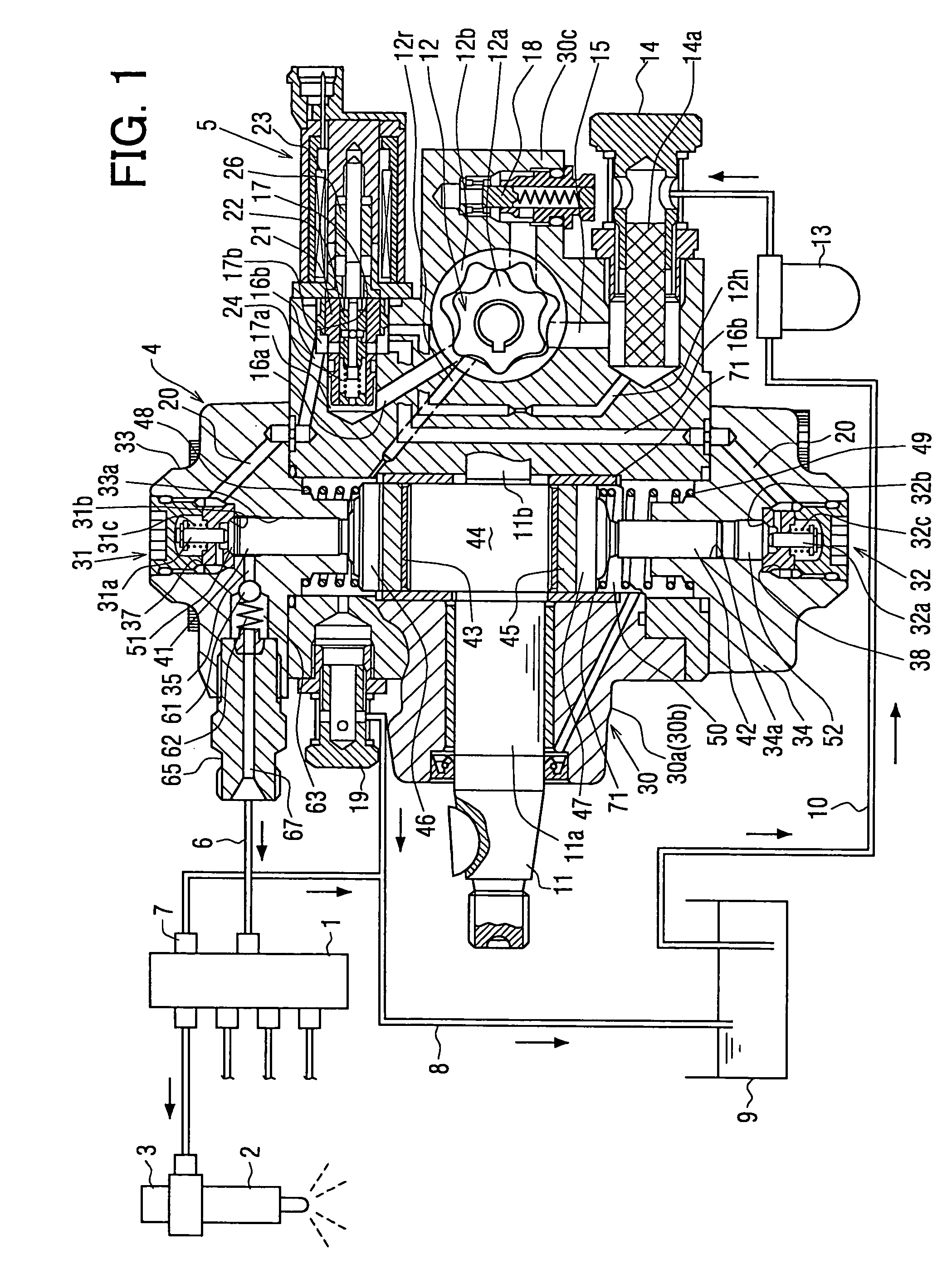
[0025]Referring to FIG. 1, a common rail type fuel injection system (an accumulation type fuel injection system) having a fuel injection pump (a supply pump) according to a first embodiment of the present invention is illustrated.

[0026]The common rail type fuel injection system shown in FIG. 1 is used in an internal combustion engine such as a multi-cylinder (four-cylinder, in FIG. 1) diesel engine. The fuel injection system accumulates high-pressure fuel in a common rail 1 and injects the accumulated high-pressure fuel into combustion chambers of respective cylinders of the engine through multiple injectors (electromagnetic fuel injection valves) 2 mounted in accordance with the respective cylinders of the engine. In FIG. 1, only one injector 2 corresponding to one of the cylinders of the four-cylinder engine is illustrated.

[0027]The common rail type fuel injection system includes the common rail 1, the multiple injectors 2, the fuel injection pump (the supp...

second embodiment

[0072](Second Embodiment)

[0073]Next, a supply pump 4 according to a second embodiment of the present invention will be explained based on FIGS. 4A and 4B.

[0074]In the second embodiment, fitting structure constituted by spline teeth and grooves shown in FIGS. 4A and 4B is employed as the connecting portion having the connection eliminating function as the safety device, instead of the thread fastening structure constituted by the male screw and the female screw of the first embodiment.

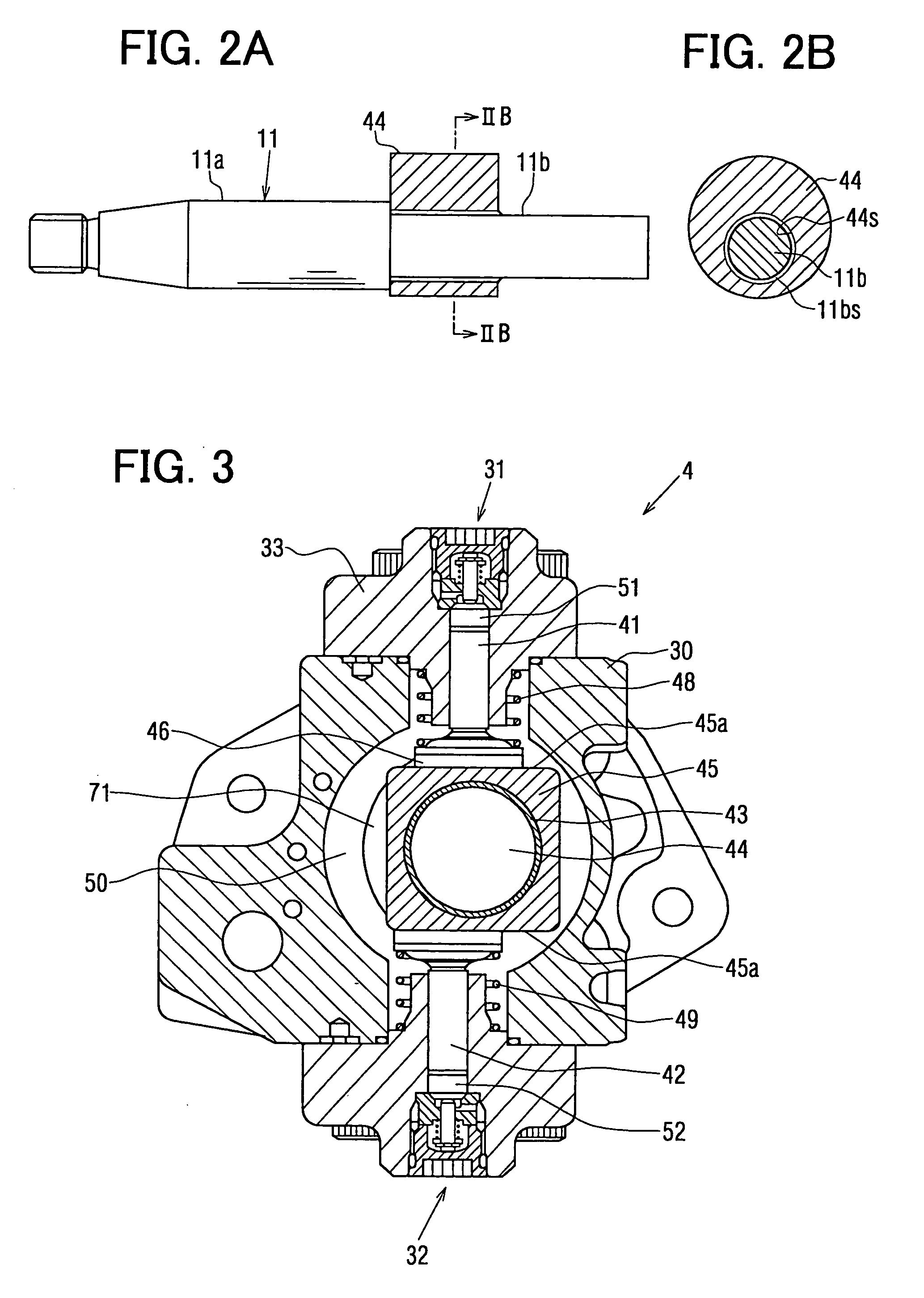
[0075]More specifically, as shown in FIGS. 4A and 4B, multiple (five in FIG. 4B) spline teeth 11bs and multiple (five in FIG. 4B) spline grooves 44s are formed on an outer periphery of the small diameter shaft portion 11b and an inner periphery of the eccentric cam 44 respectively. The spline teeth 11bs and the spline grooves 44s can mesh with each other. As shown in FIG. 4B, as radial clearance is formed between the inner periphery of the eccentric cam 44 and the outer periphery of the small diameter s...


PUM


Abstract

A fuel injection pump includes a camshaft, an eccentric cam, a cam ring, a housing and plungers. The camshaft is rotated by an engine. The cam is provided separately from the camshaft and is formed with a connecting portion connected with the main shaft. The cam rotates with the camshaft. The cam ring revolves around the camshaft so that the cam ring rotates with respect to the cam along an outer periphery of the cam. The housing rotatably houses the cam and the cam ring and is formed with fuel pressurizing chambers. The plungers reciprocate in accordance with the revolution of the cam ring to pressurize and to pressure-feed fuel drawn into the fuel pressurizing chambers. Strength of the connecting portion is set to a value lower than damage strength of the housing.

Description

CROSS REFERENCE TO RELATED APPLICATION[0001]This application is based on and incorporates herein by reference Japanese Patent Application No. 2003-349915 filed on Oct. 8, 2003.BACKGROUND OF THE INVENTION[0002]1. Field of the Invention[0003]The present invention relates to a fuel injection pump. For instance, the present invention can be suitably applied to a fuel injection pump used in an accumulation type fuel injection system of a diesel engine.[0004]2. Description of Related Art[0005]There is a fuel injection pump having a main shaft, a cam ring and at least one plunger, for instance, as disclosed in Unexamined Japanese Patent Application Publication No. 2003-148295 (Patent Document 1, hereafter) or No. 2002-250459 (Patent Document 2, hereafter). As shown in FIG. 5, a cam 144 having a circular section is integrally formed on the main shaft 110. The cam ring is rotatably fitted to an outer periphery of the cam 144 through a bush. The plunger is held inside a cylinder so that the p...

Claims


Application Information

Patent Timeline
Patent Type & Authority Patents(United States)
IPC IPC(8): F02M37/04F02M59/06F02M59/44F02M59/08F02M59/46F04B1/04F04B9/04F04B49/10F04B53/00
CPCF04B1/0413F04B53/006F04B49/10F04B9/042
Inventor HANYU, TOSHIHARU
Owner DENSO CORP
Why Eureka
Try Eureka