
Electrical device connecting a line to an electrode

a technology of electrical connection and electrode, which is applied in the direction of electrically conductive connection, coupling device connection, electrical apparatus, etc., can solve the problems of high user demands, low dimensional accuracy and high tolerance of the connecting head of the electrode, and achieves low application of force and high retention strength

Active Publication Date: 2006-07-25
NICOLAY VERW -
View PDF20 Cites 22 Cited by
  • Summary
  • Abstract
  • Description
  • Claims
  • Application Information

AI Technical Summary

Benefits of technology

[0005]Objects of the present invention are to provide a widely usable device which eliminates the disadvantages of conventional devices and which may be connected to the electrode and disconnected from the electrode with low application of force but nevertheless has high retaining strength. By preference the device is also to be suitable for wearing under clothing. In addition, the conventional insulation requirements set for medical engineering applications are to be satisfied.
[0007]The contact member, preferably, is designed to be more or less two-dimensional. The opening movement of the contact member preferably is accomplished by deflection or displacement of the contact member, more or less parallel to the surface formed by the contact member. In particular, deflection of the energy storing element and accordingly storage of energy take place when the actuating element is displaced. As a result of the opening actuation of the contact zone of the contact member, the contact pin may be introduced into the device with almost no expenditure of energy. During the subsequent resetting of the actuating element, the contact zone is brought by the stored energy into electrically conductive contact on the contact pin of the electrode. A long lasting engagement of the contact member ensuring reliable contact which subjects the contact zones to less mechanical stress is thereby obtained. High opening forces may be applied without a problem as a result of the biased operation of the actuating element. As a result, high retaining forces, and thus high contact forces, may also be provided, while the device may be easily applied to the electrode and separated from it.
[0011]To prevent straining of the energy storage of the contact element, the movement of the actuating element is limited. For this purpose, the drive element and the actuating element preferably have interacting stopping means which limit displacement of the actuating element. Optionally or in addition, the actuating element and the housing of the device also may have stopping means.
[0012]In one particular embodiment of the present invention, two actuating elements are mounted on opposite sides of the device. Consequently, application of high forces may be combined with simplicity of handling, for example, through actuation of the two actuating elements by the thumb and index finger of one hand. The two actuating elements preferably are coupled with a common drive element.
[0014]In one particular embodiment of the present invention, the housing has, on the surface facing the electrode with which contact is to be established, an elastoplastic deformable wall. The hardness of such wall is lower than that of another wall of the housing, preferably lower than that of the other housing shell. The deformable wall preferably is made of a thermoplastic elastomer. As a result of the soft elastic deformability, this wall guarantees snug fitting of the device on the electrode with which contact is to be made. Consequently, the contact reliability is increased. The comfort of wearing such devices is improved as well.

Problems solved by technology

The user places heavy demands of such devices.
An obstacle to meeting these requirements is presented by the electrodes being generally mass-produced and being made for one-time use.
For these reasons, the connecting heads of the electrodes present only low dimensional accuracy and high tolerances.
However, such electrode clamps present the disadvantage that, because of the structural configuration of the operating legs, the contact member has an external shape with multiple surfaces unsuitable for wearing under clothing.

Method used


Image

  • Electrical device connecting a line to an electrode
  • Electrical device connecting a line to an electrode
  • Electrical device connecting a line to an electrode

Examples


Embodiment Construction

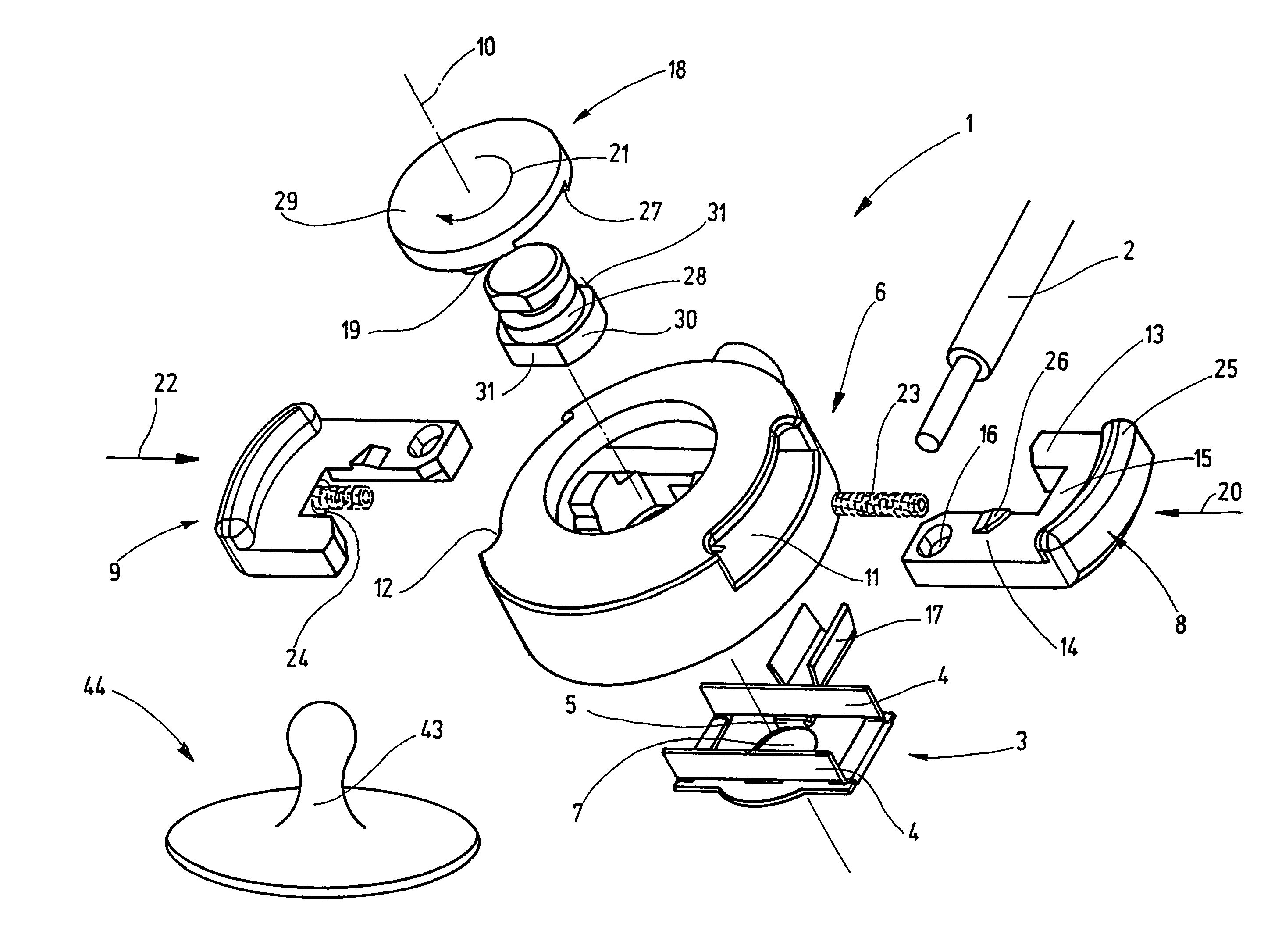
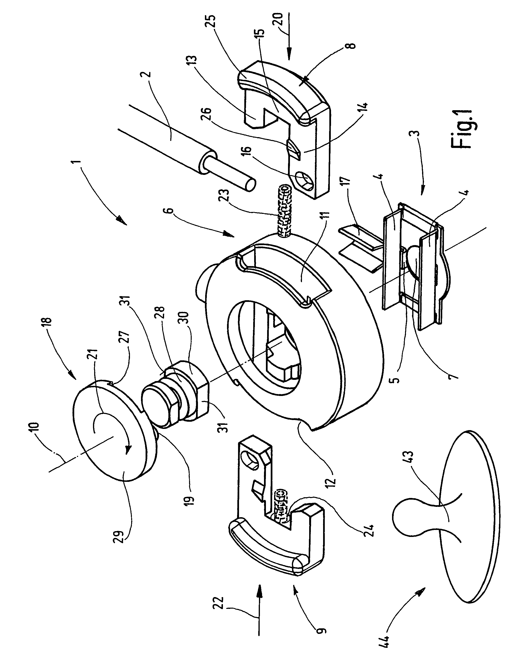
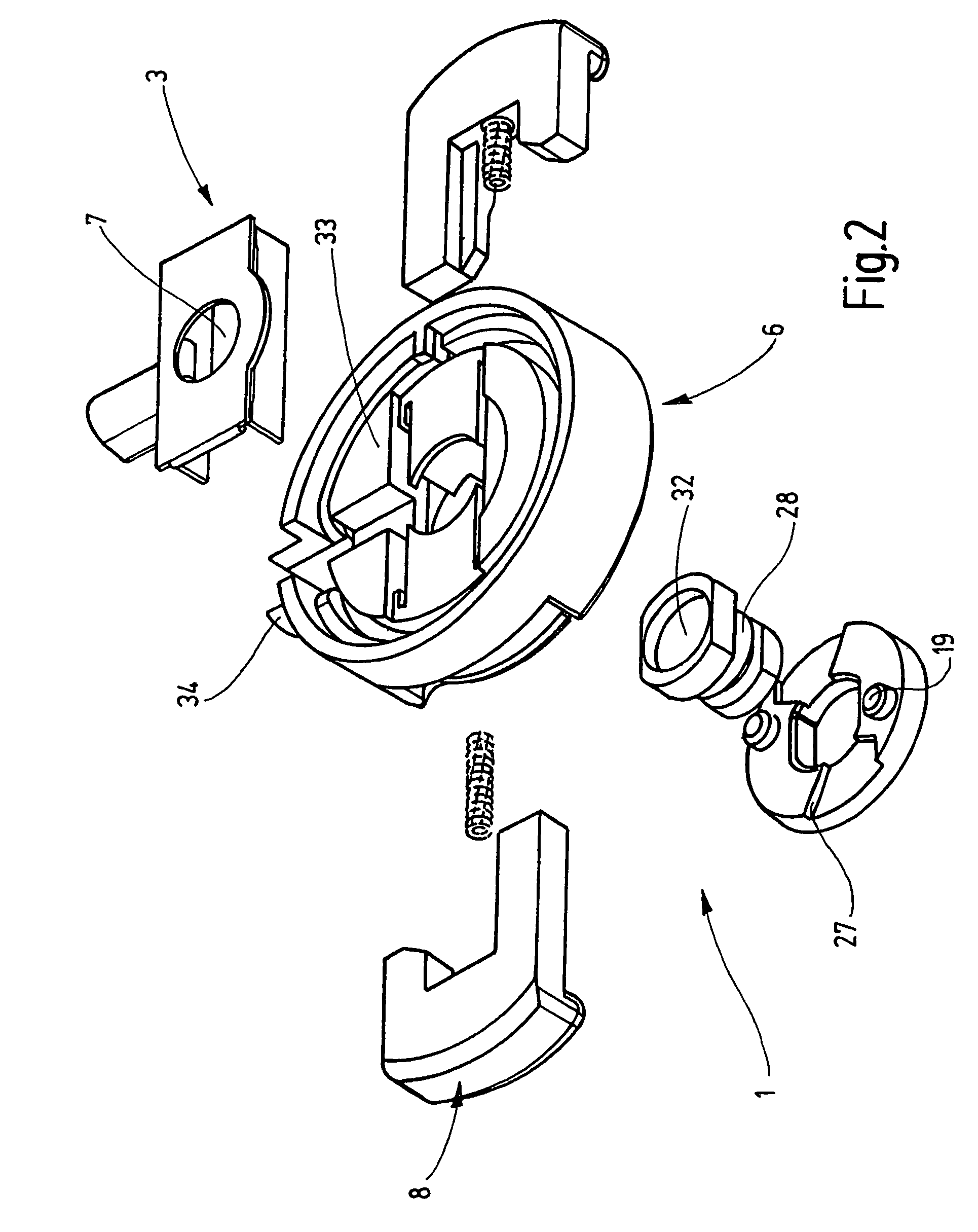
[0024]FIG. 1 illustrates the individual elements of a device 1, in an exploded view. The device 1 for electric connection of a connecting line 2 to an electrode 44, has a contact member 3 for plug connection to a contact pin 43 of the electrode 44. The structure of the contact member 3 is substantially similar that disclosed in DE 37 19 474 A1 or U.S. patent application Ser. No. 10 / 444,949 (now U.S. Pat. No. 6,780,065), the subject matter of which is thereby incorporated by reference. In particular, the contact member has two energy storing elements 4 in the form of spring legs extending parallel to each other when not extended. The spring legs form a one-piece contact bead 5 in their central area. With the bead end spaced a certain distance from the energy storing element 4, the contact beads 5 form a contact zone which, in a side view, is curved or wedge-shaped, and in a top view is straight, wedge-shaped, or curved. The contact zone extends into an opening for the contact pin 43 ...


PUM


Abstract

A device (1) electrically connects a connecting line (2) to an electrode (44), in particular a medical engineering skin electrode, with a contact member (3) for plug connection to a contact pin (43) of the electrode (44). The contact member (3) has an energy storing element (4) for spring biasing of the contact member (3) into contact with the contact pin (43) of the electrode (44). The device (1) has at least one actuating element (8,9) mounted to be deflected such that the contact member (3) may be actuated to an open position.

Description

FIELD OF THE INVENTION[0001]The present invention relates to a device for electrical connection of a connecting line to an electrode, in particular a medical engineering skin electrode.BACKGROUND OF THE INVENTION[0002]Devices for electrical connection of a connecting line to an electrode, in particular a medical engineering skin electrode, are disclosed in DE 37 19 474 A1. Such connecting devices are used, for example, for measurement of physiological signals from living beings, such as heart action voltages (electrocardiogram, EKG). The electrodes are positioned on the patient's skin, by an adhesive, for example, and are connected to an electric connecting line over which the physiological electrical signals are conducted to an evaluating device. The disclosed connecting device operates as a snap fastener connection and is snapped onto the contact pin of the electrode. The contact pin may be a separate element of the conventional electrode or may, for example, form the electrode su...

Claims


Application Information

Patent Timeline
Patent Type & Authority Patents(United States)
IPC IPC(8): H01R4/48H01R13/52H01R13/631
CPCH01R13/5224H01R13/631Y10S439/909
Inventor SCHWARZ, DIETER
Owner NICOLAY VERW -
Learn More