Valve assembly for a charging device

a charging device and valve assembly technology, applied in the direction of pivotal connections, mechanical equipment, machines/engines, etc., can solve the problems of most often unsatisfactory sealing effect of these types of valve assemblies, and achieve the effects of reducing wear, reducing leakage, and reducing the size of the valve assembly or the entire turbocharger

Active Publication Date: 2022-03-29
BORGWARNER INC
View PDF9 Cites 0 Cited by
  • Summary
  • Abstract
  • Description
  • Claims
  • Application Information

AI Technical Summary

Benefits of technology

[0011]In embodiments, which are combinable with all previously described embodiments, the accommodation region may have a second conical accommodation surface. The connecting element may be arranged in the accommodation region in such a way that a second linear contact is formed between the spherical surface of the connecting element and the second conical accommodation surface. Corresponding linear contacts result in the connection region between spindle or lever arm and the valve unit due to the interplay of spherical connecting element and one or two conical accommodation surface in the accommodation region. The connection between spindle and valve unit may thus be configured virtually free of play. In addition, an optimized, central introduction of an actuator force from the spindle into the valve unit via the lever arm may be guaranteed due to the connection via the described linear contact. This also applies in the reverse direction in the transmission of exhaust gas forces acting on the valve disk. This leads to lower leakage and consequently to higher efficiency of the valve assembly or of the entire turbocharger.
[0012]Due to the embodiment according to the invention of the valve assembly, the connecting element may be coupled to the valve unit with no or only minimal play, such that, while a certain relative movement remains possible between spindle and valve disk, clapping or rattling noises may be suppressed as much as possible. This leads in turn, together with the concept of the linear contact(s), to lower wear and consequently to a higher robustness, as lower accelerations of the components toward each other occur and thus lower applications of force and lower frictional action occur at the contact regions between the spindle or connecting element and the valve unit.
[0013]In embodiments, which may be combined with all previously described embodiments, the connecting element, designed as at least partially spherical, may be designed as at least partially hollow. The weight of the valve assembly may be reduced due to this completely or partially hollow configuration. Due to the reduced weight, the accelerated masses are additionally lower, which leads in turn to reduced wear.
[0019]In embodiments, which may be combined with all previously described embodiments with a cover, the cover may be designed as a cast part. Alternatively, the cover may be designed as a sheet metal part, in particular wherein the cover has spring-elastic properties. A biasing may be exerted via the elastic cover on the connecting element, designed as at least partially spherical, and thus the relative movement due to gas pulsation may be reduced or suppressed. This reduces frictional work and thus wear. Likewise, potential wear, which occurs during operation, may be compensated by the elastic cover. The cover with spring-elastic properties may have a centrally-arranged through passage. In particular, the cover may have recesses, which define spring-elastic arms, wherein the arms extend radially inward from an edge of the cover in the direction of the through passage. In particular, three through eight arms may be provided. In one alternative embodiment of the cover with spring-elastic properties, a bottom of the cover may have a solid part and arms machined into the bottom, wherein the arms have spring-elastic properties. This design advantageously prevents negative effects in the case of a relaxation of the spring-elastic arms. Three through eight arms may be provided.
[0025]Another general advantage of the previously described embodiments of the valve assembly according to the invention consists in that the different components may be used in the same configuration for different applications. It may thus be provided that only the size of the valve disk is correspondingly adapted to smaller and larger valve assemblies or to turbines, in which the corresponding valve assemblies are provided. The remaining components may remain the same for the different applications. Development and production synergies thus develop which may significantly reduce costs.

Problems solved by technology

The high wear, which is caused by the high number of actuations, the large forces that occur, and the high temperatures caused in this area, are problematic in these types of valve arrangements.
On the other hand, the sealing effect of these types of valve assemblies is most often not satisfactory due to the operating circumstances, for example, wear, depositions, and corrosion.

Method used


Image

  • Valve assembly for a charging device
  • Valve assembly for a charging device
  • Valve assembly for a charging device

Examples


fourth embodiment

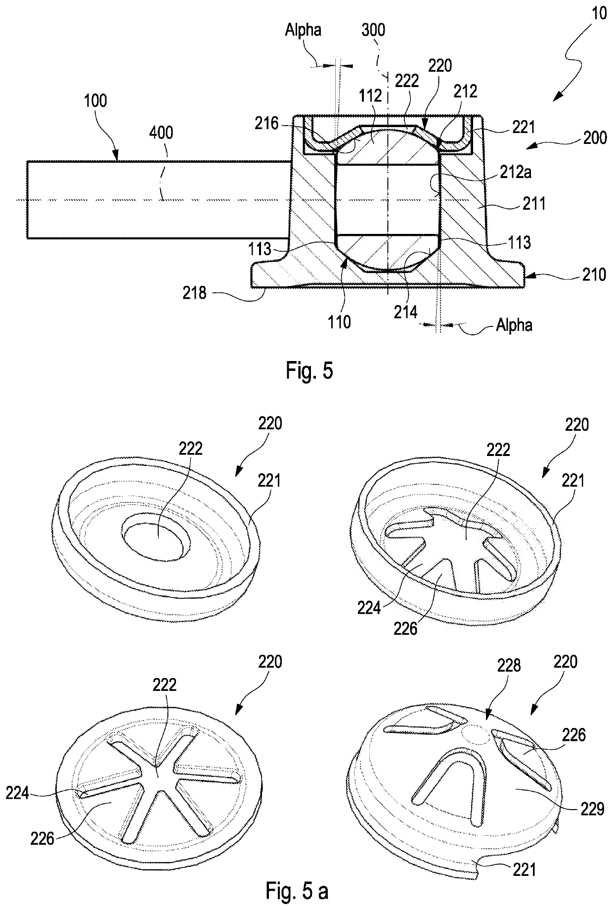
[0066]cover 220 depicted in FIG. 5a has no central through passage. The bottom 228 of cover 220 has a solid part 229 into which spring-elastic arms 226 are machined. Solid part 229 thereby also extends over the center of cover 220. For example, 3 through 8 arms may again be provided. Arms 226 may, for example, be stamped or cut into bottom 228. Prior to assembly, arms 226 are bent inward / downward in order to thereby apply a biasing force on connecting element 112 during assembly. This function will be described in greater detail with reference to FIGS. 5c and 5d. FIGS. 5c and 5d show an isometric view of previously described cover 220 and a sectional view during assembly. This means, cover 220 is not yet located in its final position. As is clear, arms 226 are already in contact with connecting element 112, as they are designed as bent inward (see left side in the image of FIG. 5d). In contrast, solid part 229 of bottom 228 is not yet in contact with connecting element 112 (however,...

first embodiment

[0072]As is shown in FIGS. 7 and 8, connecting element 112 may have a flattened portion 115 on a side facing toward valve disk 210, said flattened portion forming a stop together with valve disk 210. Due to this embodiment, a tilting of valve unit 200 relative to spindle 100 or to lever arm 110 is again limited. As in the first embodiment, the flattened portion may be arranged at an angle starting from the center of connecting element 112. In this case, at an angle gamma relative to axis 400 of spindle 100 or relative to a plane / surface which lies parallel to axis 400 (see FIG. 8).

[0073]Closing element 230 and valve disk 210 may be welded to each other, connected to each other via a press-fit connection and / or caulked to each other. For example, closing element 230 and valve disk 210 may be connected to each other by laser welding. Alternatively or additionally, closing element 230 and valve disk 210 may also be screwed to each other.

[0074]Spindle 100 and lever arm 110, or lever arm...


PUM


Abstract

The invention relates to a valve assembly (10) for a charging device, in particular for a wastegate of an exhaust gas turbocharger, comprising a spindle (100), a lever arm (110) coupled to the spindle (100), and a valve unit (200). The lever arm (110) has a connecting element (112), designed as at least partially spherical, and the valve unit (200) has an accommodation region (212) with at least one first conical accommodation surface (214) in which the connecting element (112) is arranged.

Description

CROSS-REFERENCE TO RELATED APPLICATIONS[0001]The present application is the National Stage of International Patent Application No. PCT / US2019 / 032801 filed on May 17, 2019, which claims priority to and all the benefits of German Patent Application No. 102018207989.7 filed May 22, 2018, which applications are hereby expressly incorporated by reference in their entirety.FIELD OF THE INVENTION[0002]The present invention relates to a valve assembly for a charging device, a turbine with a corresponding valve assembly, and also a charging device.BACKGROUND INFORMATION[0003]Increasingly more vehicles of the more recent generation are equipped with charging devices. In order to achieve the target demands and the legal requirements for the vehicles, it is imperative to promote development in the complete drive train and also to optimize the individual components as well as the system as a whole with respect to their reliability and efficiency.[0004]Single-stage and multi-stage, mostly two-sta...

Claims


Application Information

Patent Timeline
Patent Type & Authority Patents(United States)
IPC IPC(8): F02B37/18F01D17/10F16C11/06F16K1/20
CPCF02B37/186F01D17/105F16C11/0623F16K1/2007F05D2220/40F02B37/183F01D17/10F16K1/2014F16K1/20F16C11/069Y02T10/12
Inventor PENTH, JAKOBMUELLER, CHRISTOPHCOSSMANN, CHRISTIANUMLAUFF, ALEXANDERROTT, WERNERRAPP, FLORIANSCHOLZ, GEORGWEBER, PATRICK
Owner BORGWARNER INC
Why Eureka
Try Eureka