Fail-safe, resistive-film, immersion heater

a resistive film and heater technology, applied in the field of failure-safe resistive film and immersion heaters, can solve the problems of destroying hundreds of thousands of dollars worth of products, affecting the safety of use,

Inactive Publication Date: 2006-07-25
TREBOR INT
View PDF58 Cites 8 Cited by
  • Summary
  • Abstract
  • Description
  • Claims
  • Application Information

AI Technical Summary

Benefits of technology

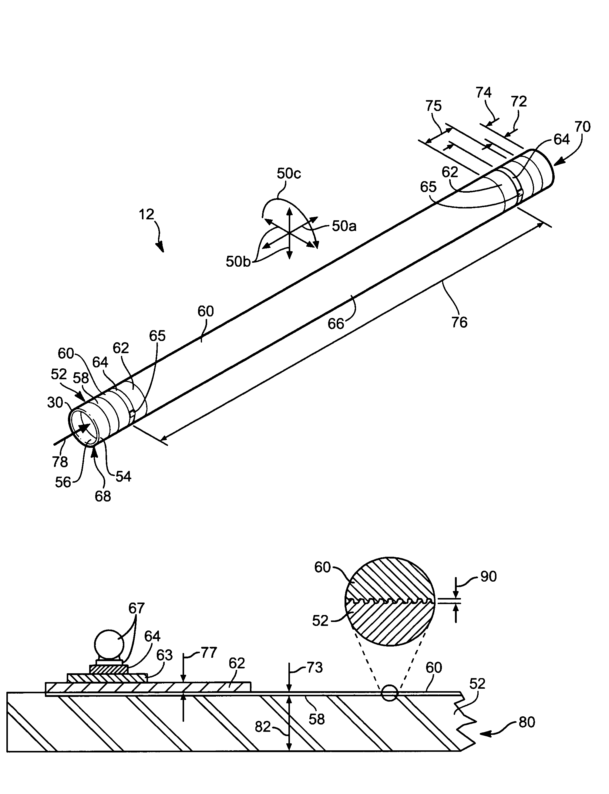
[0015]The electrical length of the heated portion (i.e. the area coated with the resistive coating) may be adjusted by application of an end coating for distributing current. Electrical current may be applied to the end the coating or directly to the resistive coating by any suitable termination. In selected embodiments, a electrical lead may be soldered directly to the end coating. In other embodiments, a conductor may be applied against the end coating. The conductor may be formed of multiple conductive strands. The strands may be formed to distribute mechanical and electrical loads substantially evenly across (typically circumfe...

Problems solved by technology

Contamination in a process fluid batch may destroy hundreds of thousands of dollars worth of product.
Several difficulties exist in current systems for heating, pumping, and carrying process fluids (e.g. acids, DI water).
Temperature transients in immersion heaters may overheat a sh...

Method used


Image

  • Fail-safe, resistive-film, immersion heater
  • Fail-safe, resistive-film, immersion heater
  • Fail-safe, resistive-film, immersion heater

Examples


Embodiment Construction

[0042]It will be readily understood that the components of the present invention, as generally described and illustrated in the Figures herein, could be arranged and designed in a wide variety of different configurations. Thus, the following more detailed description of the embodiments of the system and method of the present invention, as represented in the FIGS. 1 through 24, is not intended to limit the scope of the invention, as claimed, but is merely representative of the presently preferred embodiments of the invention.

[0043]The presently preferred embodiments of the invention will be best understood by reference to the drawings, wherein like parts are designated by like numerals throughout. Those of ordinary skill in the art will, of course, appreciate that various modifications to the detailed schematic diagram may easily be made without departing from the essential characteristics of the invention, as described in connection with the Figures. Thus, the following description ...


PUM


Abstract

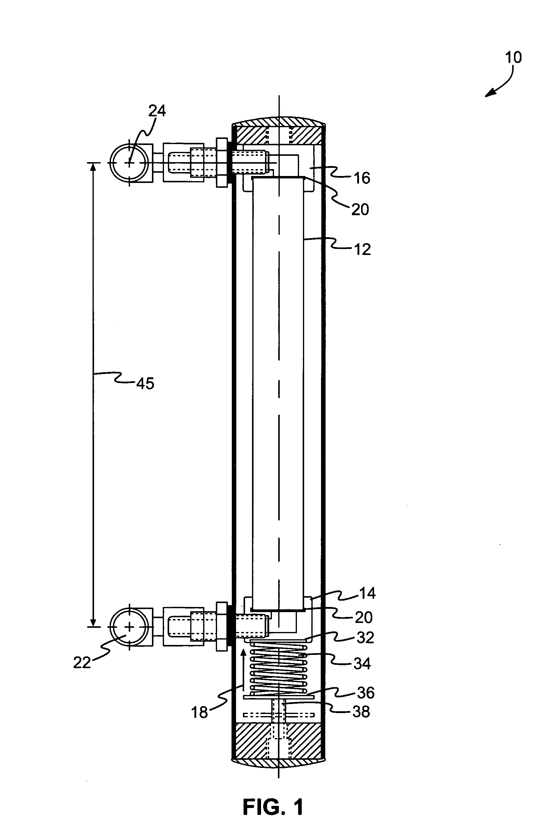
A heater comprising a conduit made of corundum (e.g. synthetic sapphire) and having a wall forming a closed cross-section with an interior surface, and an exterior surface. At least one of the interior and exterior surfaces may have a roughened portion comprising inclusions and corresponding protrusions formed substantially continuously therethroughout. An electrically resistive coating may extend substantially continuously over, in, and around the inclusions and protrusions of at least a part of the roughened portion to form a conformal cross-section having a thickness selected to promote bending thereof to accommodate annular expansion and contraction occurring in response to a differential in the coefficients of expansion between the electrically resistive coating and the conduit.

Description

RELATED APPLICATIONS[0001]This Patent application is a continuation-in-part of and claims priority to U.S. patent application Ser. No. 10 / 736,220 filed on Dec. 15, 2003 now abandoned and entitled ELECTRICAL, THIN FILM TERMINATION, which is a continuation of Ser. No. 10 / 218,194, filed Aug. 12, 2002, now U.S. Pat. No. 6,674,053 issued Jan. 6, 2004 and entitled ELECTRICAL, THIN FILM TERMINATION, which is a continuation of Ser. No. 09 / 882,455, filed Jun. 14, 2001, now U.S. Pat. No. 6,433,319 issued Aug. 13, 2002 and entitled ELECTRICAL, THIN FILM TERMINATION, which is a continuation-in-part of Ser. No. 09 / 738,724, filed Jan. 15, 2000, now U.S. Pat. No. 6,580,061 issued Jun. 17, 2003 and entitled DURABLE, NON-REACTIVE, RESISTIVE-FILM HEATER, which claims the benefit of U.S. Provisional Patent Application Ser. No. 60 / 179,541 filed on Feb. 1, 2000 and entitled DURABLE, NON-REACTIVE, RESISTIVE-FILM HEATER.BACKGROUND[0002]1. The Field of the Invention[0003]This invention relates to electrica...

Claims


Application Information

Patent Timeline
IPC IPC(8): H05B3/46H05B3/02
CPCH05B3/46H05B3/82H05B2203/021
Inventor BLACK, STEVEN A.
Owner TREBOR INT
Why Eureka
Try Eureka